soapfoot
Well-known member
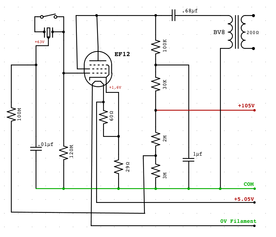
beautiful. Thanks so much. I'm working on a schematic right now.


soapfoot said:So in your opinion, for my project-- with a regulated 6V supply for the EF12 heater, I can assume a very small load for the 105V supply for the rest of the mic?
0dbfs said:Please post your schematic when you are ready!
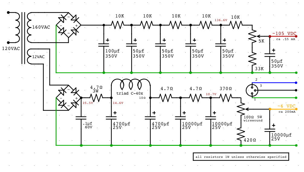
Should be small compared to the heater current but will need to be close to compute the voltage drop across the CRC in the PSU.
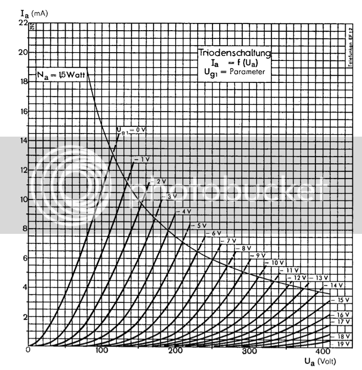
I believe the plate-current is largely dependent on the cathode/grid operating points and if you know plate current and voltage-drop you can then figure out the load. This gets into analyzing the tube data sheets (which there may be none for an ef12 in triode mode).
Will you be using fixed bias with the cathode seeing a fixed voltage between heater return and 0V or will you use an auto-bias scheme maybe with bypass cap?
If the cathode bias is coming from the heater line a regulator may introduce undesirable artifacts into the grid circuit.
soapfoot said:Ah, I see. This gets more complicated than I thought!
Hum. It's because the heater line has to have absolutely no ripple if the cathode is referenced to it or it interacts with the grid operating point WRT the cathode. And if the grid voltage moves... That turns into audio.soapfoot said:Would love to hear more about this. What type of undesirable artifacts are you talking about?
")
0dbfs said:Please post your schematic when you are ready!
Enter your email address to join: