Spot the clone...

GroupDIY Audio Forum

Help Support GroupDIY Audio Forum:

This site may earn a commission from merchant affiliate links, including eBay, Amazon, and others.

SSLtech

Well-known member
Joined
Jun 3, 2004
Messages
5,447
Location
Florida (Previously UK)
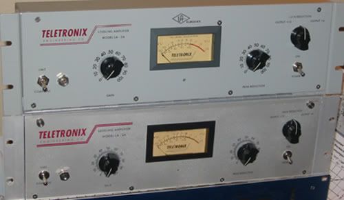
Not all that tricky, but I had to take the pic!

2LA2small.jpg


Keith
 
Cool Keef!
I actually like the bottom one better than that puke green.

Here's an NOS box for you.
Now you can put that bad boy on evilbay and collect three grand!


:guinness: :guinness: :guinness: :guinness:

box.jpg
 
Screw you, Scenaria!

..just for that you have to bring in all of your Bloos and give them to me...

Or at least line them up for a photo session, to make people's jaw drop!!!

Keef
 
The top one is a UA reissue (hence the 'UA classics which spoils the front panel) and is in the same grey paint that the very first run was made in. After that they went to silver (better looking in my opinion).

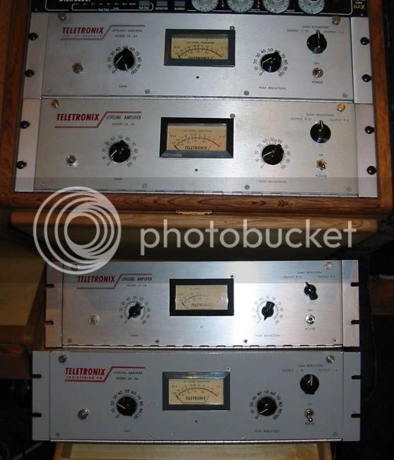
Just for reference, here's some original units which I recently worked on:
Cali-all-4.jpg


The bottom unit of this stack of four is a grey-paint version. (Note that the beede meter also has the grey surround as in the current UA reissue, but without the abomination of the "UA classics" logo above the meter.)

Looking at the bottom two in this picture gives a similar silver version /grey version comparison to the silver SSLtech clone/grey UA reissue in the first picture... Quite nice...

2LA2small.jpg


Keith
 
One other subtlety: the original grey units had "curved-bend" rack ears where they meet the front panel, the silver versions had sharp 90° corners. I kept that detail accurate on my clone, but I didn't 'open up' the rack mounting holes for the rack screws into "slots", I left them as "holes". This is one area where the original ones sometimes bend. It also makes the clone easier to identify.

Keith
 
I did run sweeps, sory I forgot to reply to that!

The compression sweeps were absolutely and completely accurate. I won't say "identical" because no two of the many many original LA-2a's which I compared actually measured the same!

The 'limiter response' control has an effect, so too does the 'limit ratio set' resistance (R7). Switching out the T4 means that both R7 and R25 have to be re-set, and even once the response tweaker has been set, no two still produced the same curves!

However, superimposing the different sweeps one atop the other, there was a range and a trend of behaviour, and the clone was dead-spot in the middle!

Noise measured without the T4B fitted was lower in the (all carbon comp except for R4-R7 metal film used where the signal is 'fragile') clone, and distortion was also lower.

I didn't have a camera when I ran the sweeps, (Neutrik A2, no way to save sweeps) but I also ran a couple of the BLOO versions and they were also right in the middle of the 'range of authenticity'.

Keith
 
Keith,

Could you elaborate on the response characteristics - are there consistent traits?

Does this resemble what you're seeing: http://www.vacuumbrain.com/The_Lab/TA/Rons_LA2a/la2a_sweeps.jpg

Is there any tuning you're doing with regard to the vari-caps or elsewhere?

Thanks,

Ron
 
Those are the kind of response curves which we got by sweeping through the freq sweep at the same input level, but with varying settings of peak reduction. The limiter response control affected the HF/LF balance. T4 module swaps had a slight but not gigantic effect.

We also got very different characteristics from sweeping the amplitude at a constant frequency, measuring the corve of the 'limit' setting. some sent from the 1:1 straight line through a soft-ish-knee, into limit as a horizontal line, (eventually rising at 1:1 again when the LDR saturates) others curved and dipped down into "past-infinity" before gradually curving upwards again. some gave a line closer to horizontal, but never actually achieving full limit.

The 'horizontality' of the line is alterable by varying R7. The linearity is not, and is a characteristic of the T4 module itself. CJ's T4 measured straight and linear once R7 had been set. A few of the UA reissue T4s were curved like a sad face, one had an s-bend in it. A few of the original vintage T4's tested closer to CJ's than to the reissue UA...

once again... WELL DONE CJ!!!

There was more... much more that was measured and listened to, too much to get into right now. -Suffice to say we're getting a pretty good handle on the whole LA-2a clone thing, and it looks like while UA have just as much -or possibly more- knowlege of the subteleties and artifacts, they appear to be letting a few things slip in the interests of consistent and expedient production, so they can meet people like Guitar Center's Wal-Mart like homogenised-volume-production requirements.

I should clarify the above statement; It is not a slam of UA, just an observation that they face pressures and delivery/manufacturing complications which the average competent DIY'er will shrug off as being part of the game. They do a good job. A little care and attention though, and most DIY'ers can do a better job.

Keith
 
Keef,

VERY NICE!

I have this friend down here that did a LA2, sounds very nice. When comparing to the UA reissue he told me that it sounds less pleasant to his ears, some kinda of bump in hi frequency on his(around 6k to 10k they told me).

Do you have any clue? I have asked him to plot some sweeps but I dunno he can make it before returning the UA one (it's loaned...).

He followed Kent S. plan (jensen transformers...) and got the UA T4 cell, new one.

Anyone else have inputs about this ?

thanks!
Fabio
 
prob the hi freq trim...

the ceramic cap... just tell him to turn the ceramic cap a quarter turn counter clockwise.. he might have a hi bump
 
Keith,

Thanks for the info - interesting stuff there.

So, in your estimation, my sweeps indicate nothing requiring tweaking - you'd be satisfied with that response?

Aside from R7, how are you calibrating - what are you looking for?

Lastly, are you planning on making your test data available to us here?

Thanks again,

Ron
 
Your sweeps are indeed typical, nothing to fix there.

R7, if you don't have the ability to plot rising-amplitude-at-fixed-freq sweeps, do the following:

Using a sine wave (1kHz is perfect) through a volume control, set the volume control so that it's about 20dB below maximum output, then set the peak reduction control of the LA-2a so that it is just at the threshold of gain reduction. Switch the output meter to '+4' and adjust the gain so that the signal is about 0VU. Leave the two front panel controls fixed in this position.

With the switch set to compress, turn the volume control on the incoming oscillator signal all the way off. Now, watching the meter carefully, raise the incoming signal volume. Beyond zero, the signal should climb steadily, but slightly, and should continue to climb as the incoming volume is raised.

Return the volume to off and wait 60 seconds for the LDS's to de-soak.

With the switch set to limit, watching the meter carefully, raise the incoming signal volume. Beyond zero, the signal should stop, neither rising nor falling. This is the 'ideal' straight line. If the signal rises steadily but slowly (more slowly than in 'compress' mode) then R7 is too small and should be increased. If the metered output signal actually goes *DOWN* as the incoming signal is increased, then R7 is too large. (this is "past-infinity" compression). If the signal first rises, then goes down, the rises again you have an s-curve... try swapping the LDRs over between metering and signal attenuation positions, and see if things are better that way round. If so, you'll need to re-calibrate R25 as well, to make sure that the meter tracks.

BTW... R25 (meter tracking) should be set in compress mode, not limit.

Keith
 
Back
Top