What gets damaged if a lunchbox is underpowerred? Modules,lunchbox,both or none?

GroupDIY Audio Forum

Help Support GroupDIY Audio Forum:

This site may earn a commission from merchant affiliate links, including eBay, Amazon, and others.

canidoit

Well-known member
Joined
Apr 6, 2009
Messages
1,169
Location
Australia
I can't find the exact current draw for one of my modules so I would like to know if a lunchbox only pulls out 480mA and you have modules that total to about 520mA-620mA what usually happens in this scenario?

- The modules get damaged and if so, is there a preference to which module get damaged, like the highest current module
- The lunchbox gets damaged
- None will get damaged and the lunchbox will just shut down
- The lunchbox and modules will both get damaged

Thanks
 
I say... (E) none of the above. Voltage would drop and modules would not perform correctly, but nothing would be damaged.
Although possibly something in the psu would fail, so I assume no liability for this answer.
My experience with drawing too much current from regulators is that they auto protect to a degree. They could melt also though.
 
Assuming the regs are some 78-78xx or LM317's, they won't go into current protection at 600mA; they are rated at 1.5Amp.
They may go into thermal protection if insufficiently heatsinked; but apparently the limiting factor is the xfmr.
The regs would go out of regulation and deliver basically the unreg voltage minus about 1-2V. There would be a lot of ripple and the modules would hum.
That's about it; it can do no harm to anything (except your ears).
 
canidoit said:
I can't find the exact current draw for one of my modules so I would like to know if a lunchbox only pulls out 480mA and you have modules that total to about 520mA-620mA what usually happens in this scenario?

Why can't you find the current draw for the module?  If you have a bench supply simple clip onto the lose module PSU pins with alligator clips and put a multimeter in line. If you don't have a bench supply just open up your racks PSU and use little jump leads to get to your module.  Or be a little more professional and make an extension card with bits from Jeff/Cemal/Volker.  This doesn't need to be a terrifying unknown.

Cheers,
Ruairi
 
ruairioflaherty said:
canidoit said:
I can't find the exact current draw for one of my modules so I would like to know if a lunchbox only pulls out 480mA and you have modules that total to about 520mA-620mA what usually happens in this scenario?

Why can't you find the current draw for the module?  If you have a bench supply simple clip onto the lose module PSU pins with alligator clips and put a multimeter in line. If you don't have a bench supply just open up your racks PSU and use little jump leads to get to your module.  Or be a little more professional and make an extension card with bits from Jeff/Cemal/Volker.  This doesn't need to be a terrifying unknown.

Cheers,
Ruairi
I thought it would be something that the designer would know but Il give it try.

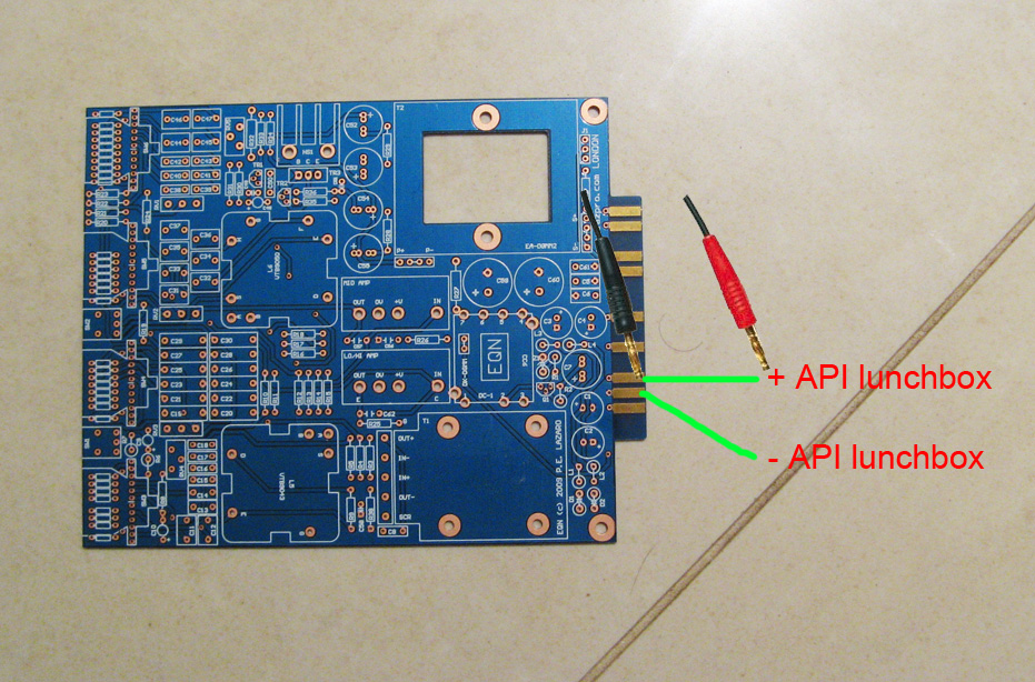
So I would do something like this with my multimeter? I didn't think my multimeter could measure current?
testCurrent.jpg

If the positive goes to that part of the PCB, I apply my multimeter like shown on the pic and it will give me the milliamps?

Thanks
 
That's a short circuit. Exactly the same as touching the tips of your multimeter together and does nothing.

Look at your multimeter manual and find out how to set it into measuring current. this usually means changing the pins of the banana plugs, and setting the dial into current mode.

For measuring current you will insert the multimeter in series with the voltage pin. That means the current goes through your multimeter, replacing that green line you have drawn. Then measure the negative pin separately the same way.

When the multimeter is set up for measuring current, do not try to measure the potential between +/- rails or ground. Fuses will break, or at worst, stuff will burn.
 
Thanks Kingston.

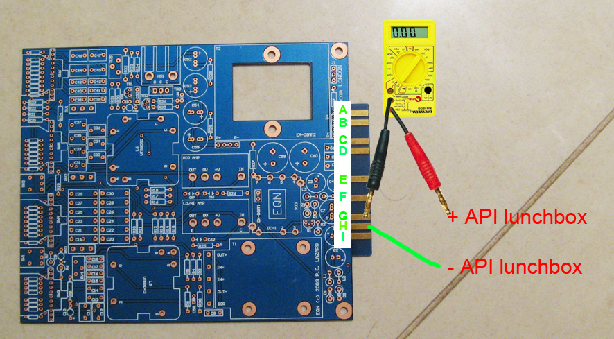
So you mean something like this:
testCurrent2.jpg


Do you know which PCB metal tab bit on the PCB I connect the multimeter to? A, B, C, D, etc.
 
canidoit said:
Do you know which PCB metal tab bit on the PCB I connect the multimeter to? A, B, C, D, etc.

just the way you have it.  the 12'th finger (G, by your labeling) is your +16V power rail.  since it's bipolar, i suppose you could also check the -16V rail (14'th finger, or letter I here) in the event that current draw is asymmetrical. by the api standard, the 13'th finger (H) is actually power ground, contrary to your labeling.
 
As Kingston said check your DMM manual.

Most current readings are made by placing the DMM in series with the load under test after changing your leads to a different position.

Your first picture the current would follow the past of least resistance and go through the solid wire, your second picture is correct as far as how to use most DMM's are concerned.

There are some clamp on meters that can see current most of the ones I have seen are inaccurate at small current.

 
kazper said:
As Kingston said check your DMM manual.

There are some clamp on meters that can see current most of the ones I have seen are inaccurate at small current.

Clamps only work on AC....and only accurate @ the rated frequency...its a transformer !
DC requires a "shunt" resistance to measure a voltage across...thats what the meter has inside..
 
Clamp-on ammeters do exist for DC.  I have a Tenma AC/DC clamp-on that includes several ranges from 0-400mA to 0-40A DC.  Can be handy for getting a rough current check from a circuit, although for anything requiring real accuracy I'll always use a DMM.
 

Latest posts

Back
Top