1176 in 51x/500 format, or 51X-F76 Build Support Thread

GroupDIY Audio Forum

Help Support GroupDIY Audio Forum:

This site may earn a commission from merchant affiliate links, including eBay, Amazon, and others.
Just want to comment on the GR_SCALE trimmer's orientation vs the 0GR trimmer's orientation. 

this picture shows igor orienting them the same way.  but the silk screen on the PCB (v1.4) shows them facing opposite directions:

P1050937.jpg


MOM_V2.jpg
 
iirc i think reading that with the kits he provided some Transistors, that had pins reversed so that's what you see in his picture, check first page on the support thread or the files about the build.....

EDIT: Reply#2
 
I built up Igor's Input amp today for the kit.  My order for building was just like the Gar2520s

1.  place the pins in the sockets on the main PCB.  stick the DOA boards on top of the pins and solder.
2.  the little ceramic capacitors first (C1, C2, C3)
3.  R5 comes next
4.  the two BD139s are next.  Be careful about orientation.  for the BD139s supplied with my kit, they were not beveled so, i had to test them to find out which pin was the emitter.  For me, the silk screen on the BD139s ended up facing C1 and C3.
5.  D2 and D3 come next.  Note the way igor combined them in this post:  http://www.groupdiy.com/index.php?topic=43338.msg567412#msg567412
6.  T1, T2, T3 are next.
7.  R8, R1, R4, R2 and R3 in that order.
8.  The trimmer R7 is next. 
9.  R6 and R9 come next.
10.  D1, the Zener diode is last.

a fairly painless build, although small.
 
mulletchuck said:
Can anyone tell me what to order for the Q1/Q10 sockets on the main PCB?    the little 3-pin sockets for easily swapping out those transistors. 

You need this, or if you have nothing else to order, just gently dismantle a IC socket, be carefull because one or the other
option are tricky to break, because you can loose the pin while doing so, better always cut one pin more and take
the last one out after...


http://www2.mouser.com/ProductDetail/Mill-Max/800-10-064-10-002000/?qs=sGAEpiMZZMs%2fSh%2fkjph1trRw3Iqu89Lvlk1mjsAI7Bw%3d
 
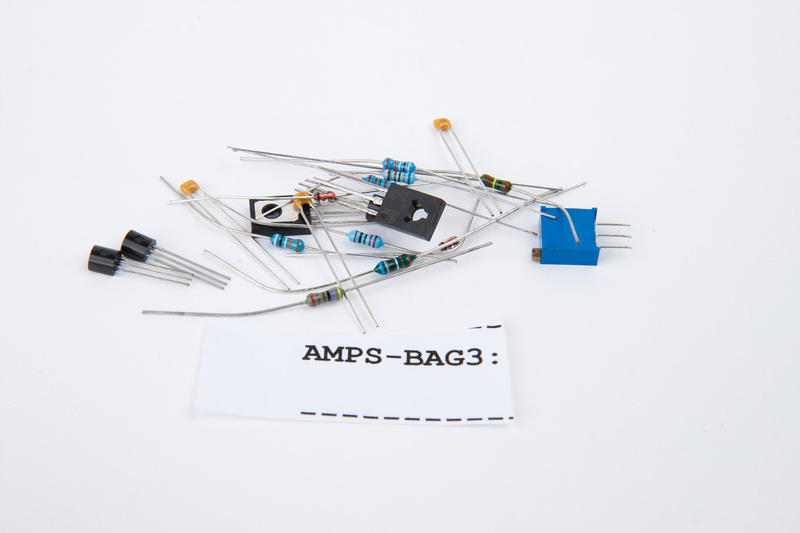
A little more progress on my f76 build. . . I heard rumor from a few people that there were some mechanical assembly difficulties with the kit, so I decided next, I would try to assemble the major components to discover what those difficulties are and figure out a way to shift the tolerances so the build will be as polished-looking as I can manage.  I thought this might be important before I started populating the PCB's so I do not accidentally install a mis-aligned component that is difficult to remove and adjust.

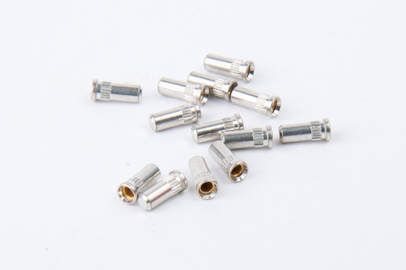
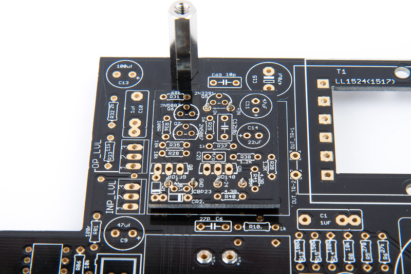
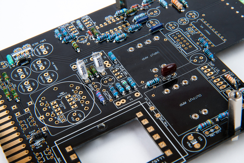
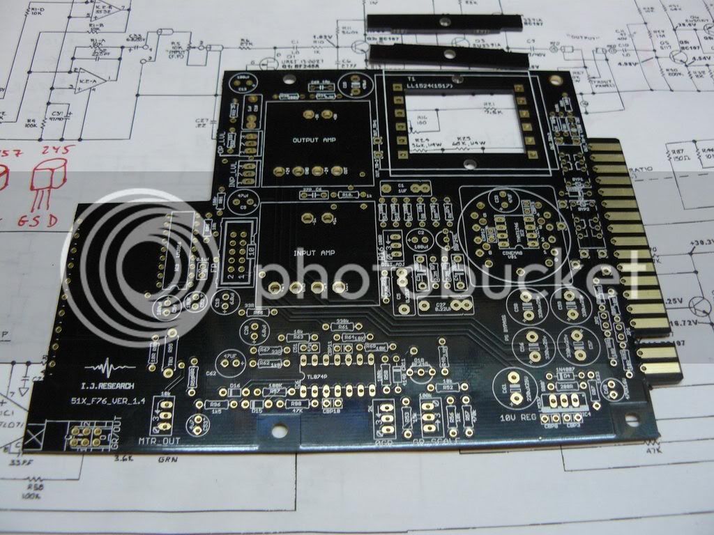
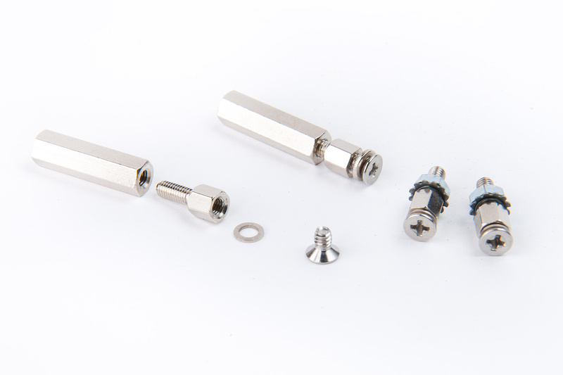
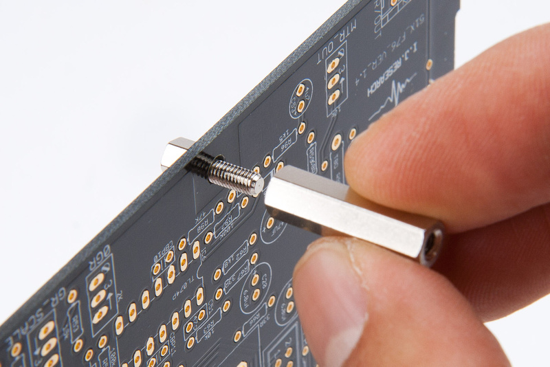
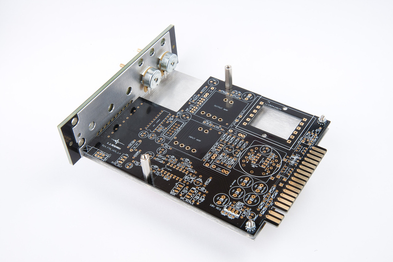
First, I located the main PCB mounting hardware.

p94685931-4.jpg


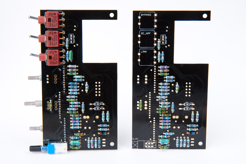
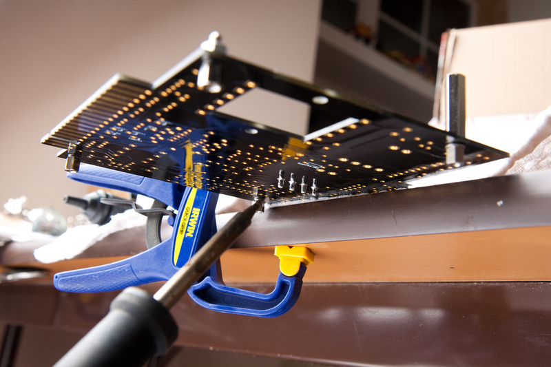
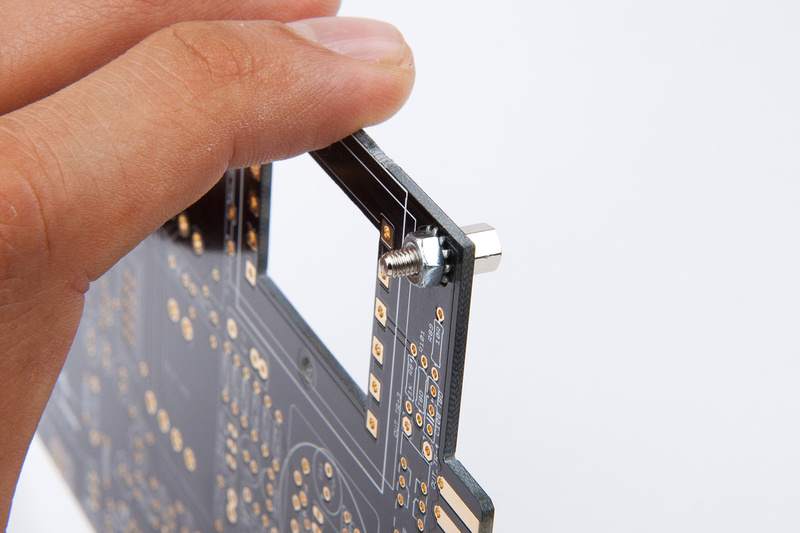
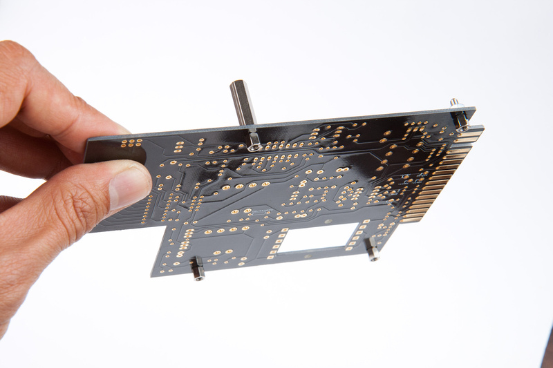
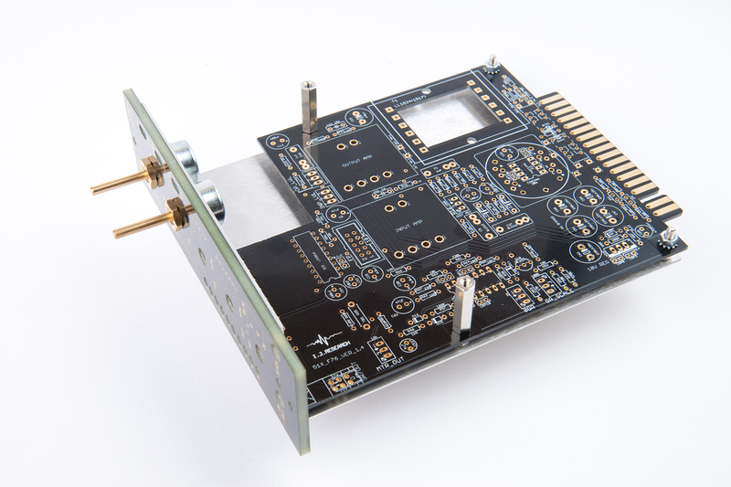
And proceed to temporarily mount the main PCB.

p355834183-4.jpg


p96677933-4.jpg


p301254899-4.jpg


p293793600-4.jpg


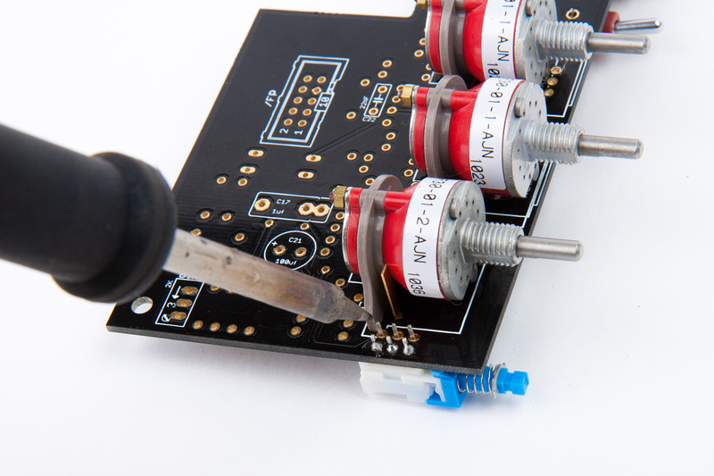
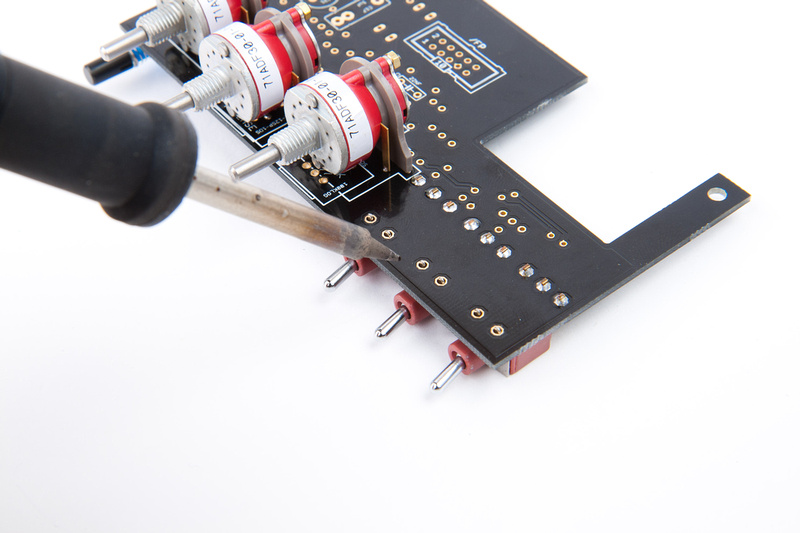
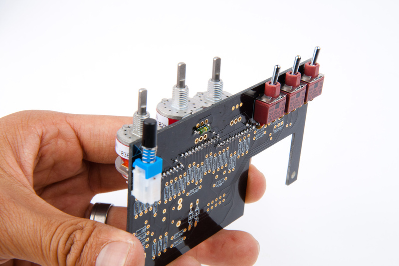
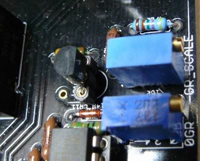
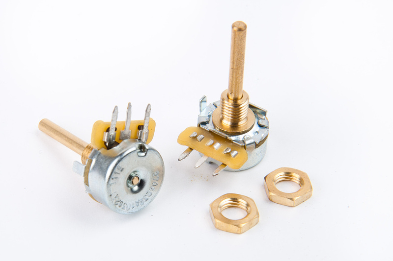
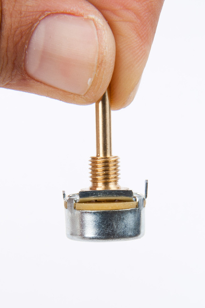
Next, I located my input and output pots along with their nuts.

p484473827-4.jpg


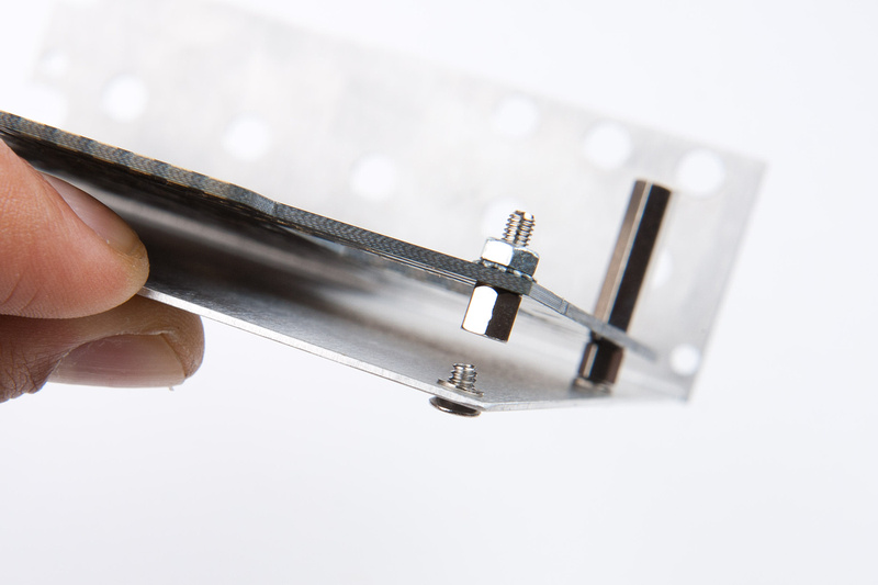
And, discover that they will not mount flush to the L-bracket without slight modification.
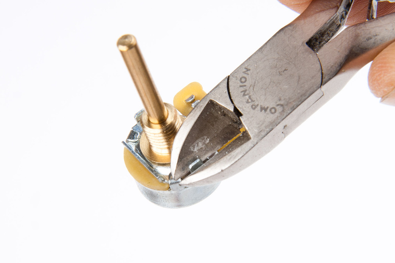
p8746091-4.jpg


so, I modify.

p31803881-4.jpg


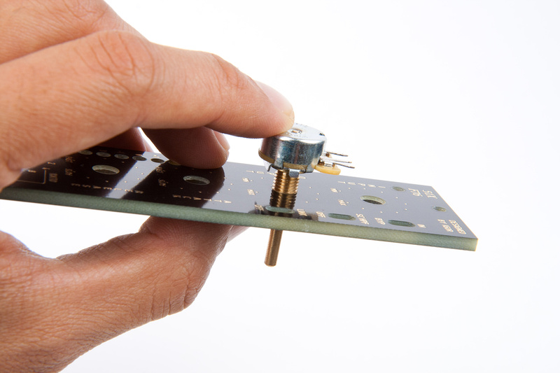
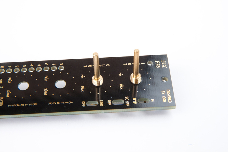
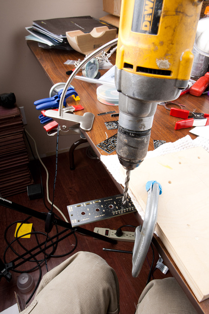
Next, I discover the pots will not fit into the faceplate. . .

p4644233-4.jpg


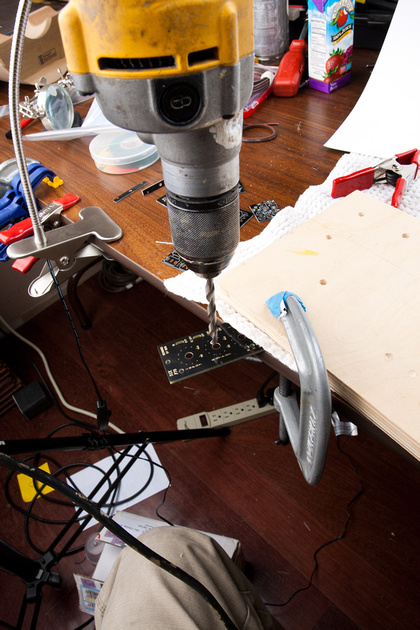
So, I use a 1/4" drill bit and open up the holes slightly.  I ran my drill backwards to get a smoother cut and try not to damage the nice faceplate.

p452549159-4.jpg


no problem now.

p343427181-4.jpg


p442108971-4.jpg


p150033561-4.jpg


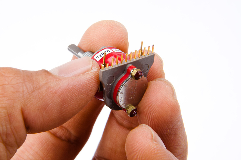
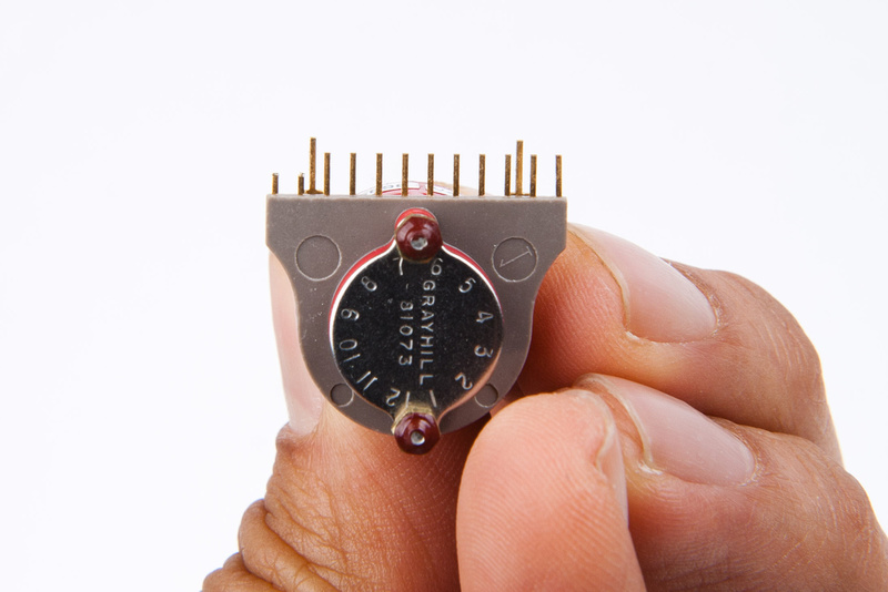
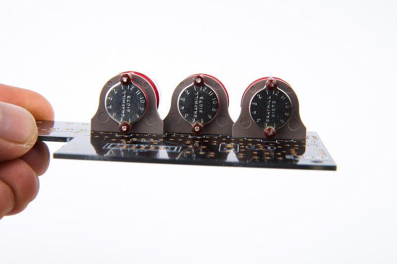
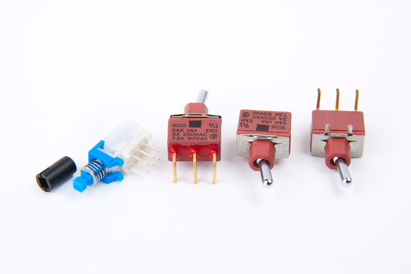
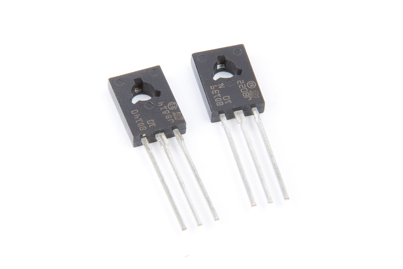
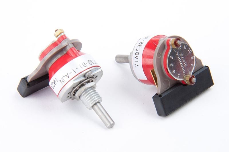
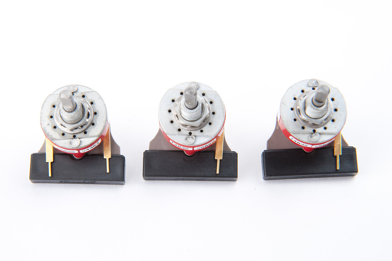
Next, I locate my grayhill switches

p135062774-4.jpg


I worried for a moment that I would confuse the 2 types of switches and then realized that they have different mounting tabs. . . there is no way to install them in the incorrect locations  ;D

p526042149-4.jpg


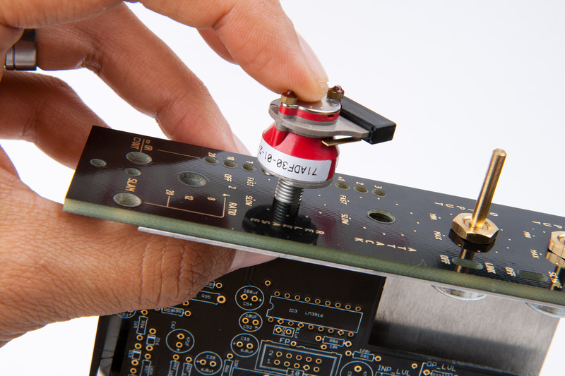
But, unfortunately, they also do not fit on the faceplate. . .

p203920152-4.jpg


So, a bit more drilling for the grayhill switches.

p421083503-4.jpg


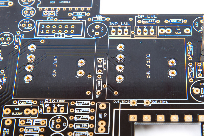
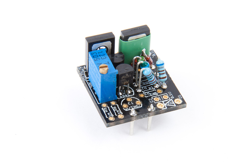
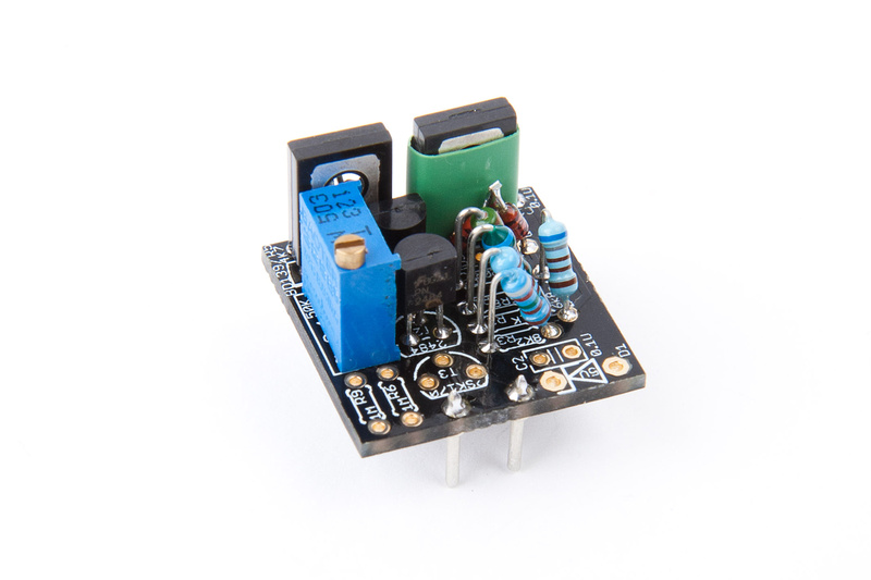
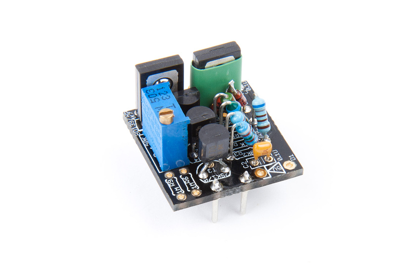
At this point, I take a step back and decide that I should align the main PCB components before moving up to the secondary PCB and the grayhill switches, so I put the grayhills aside and concentrate on the main PCB components.

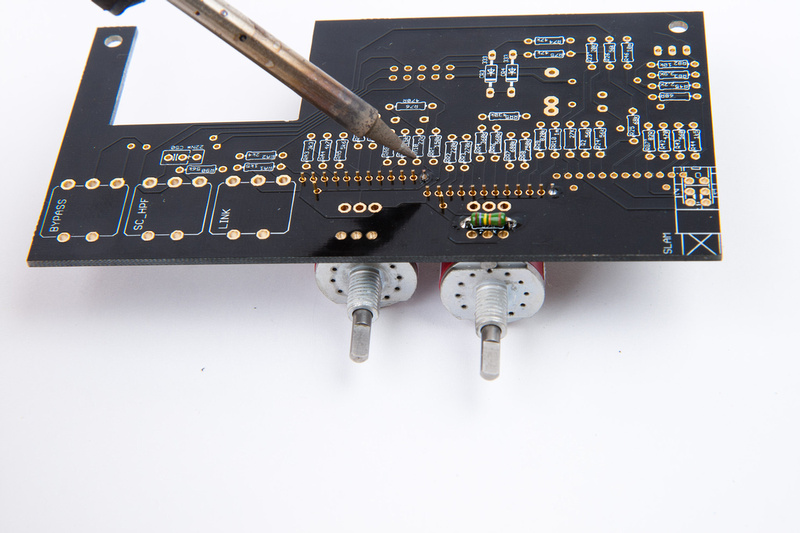
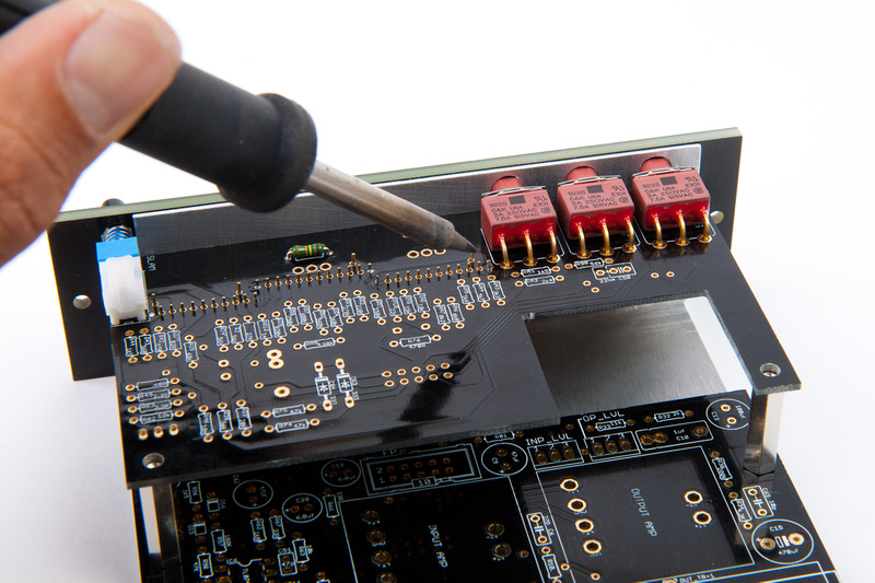
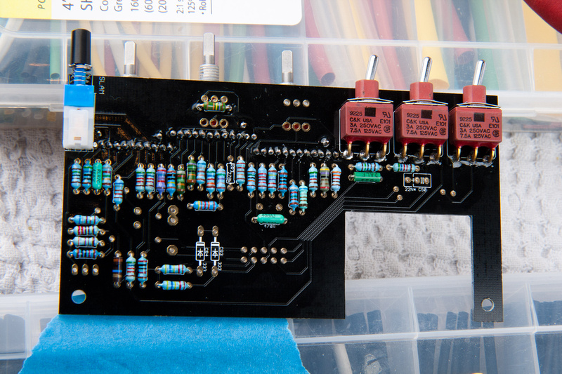
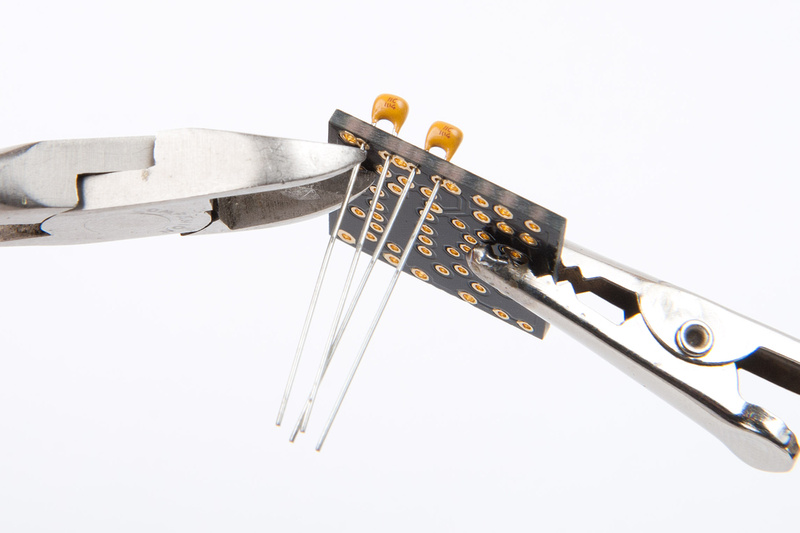
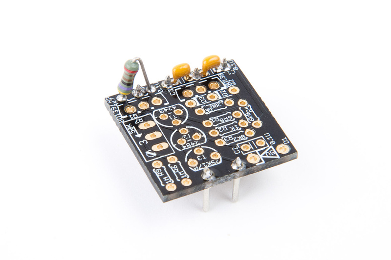
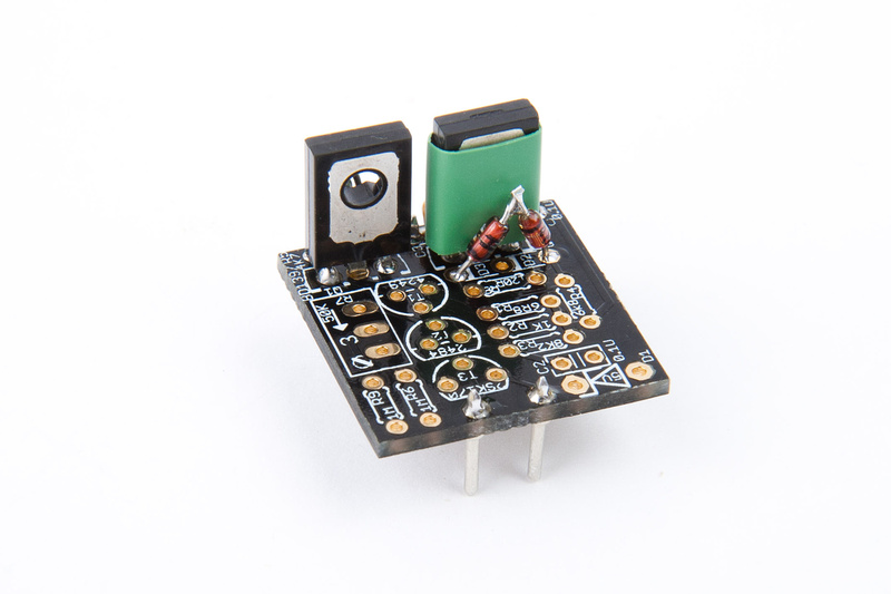
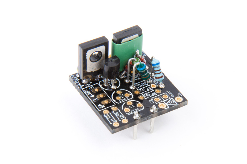
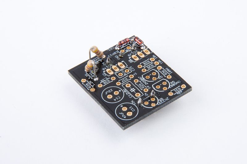
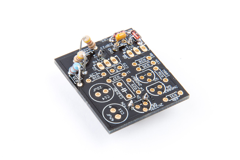
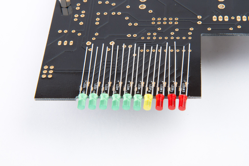
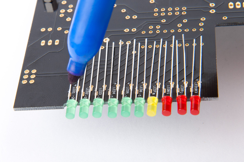
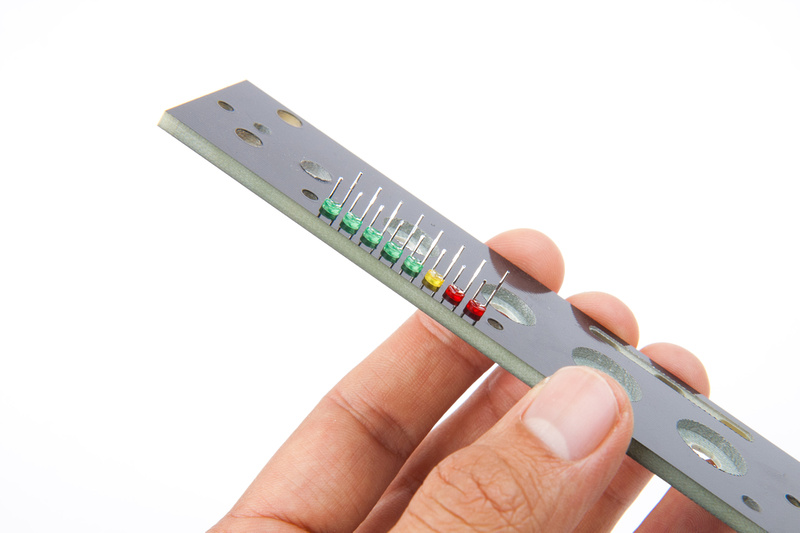
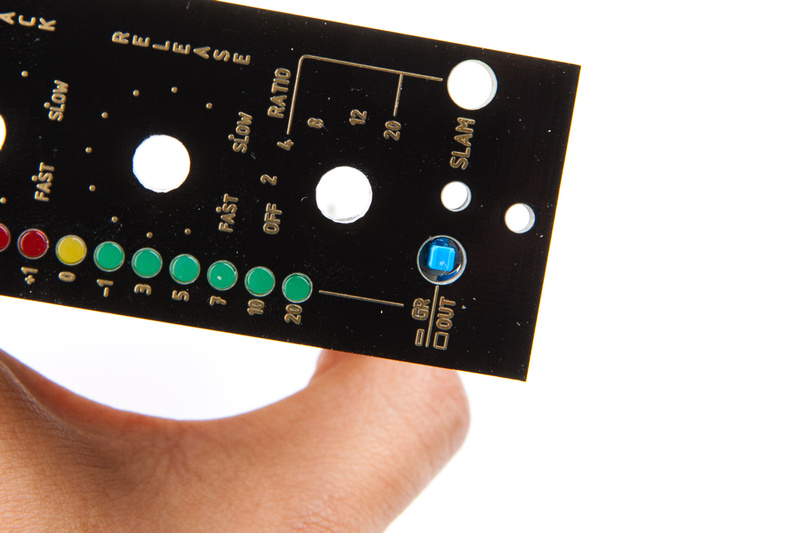
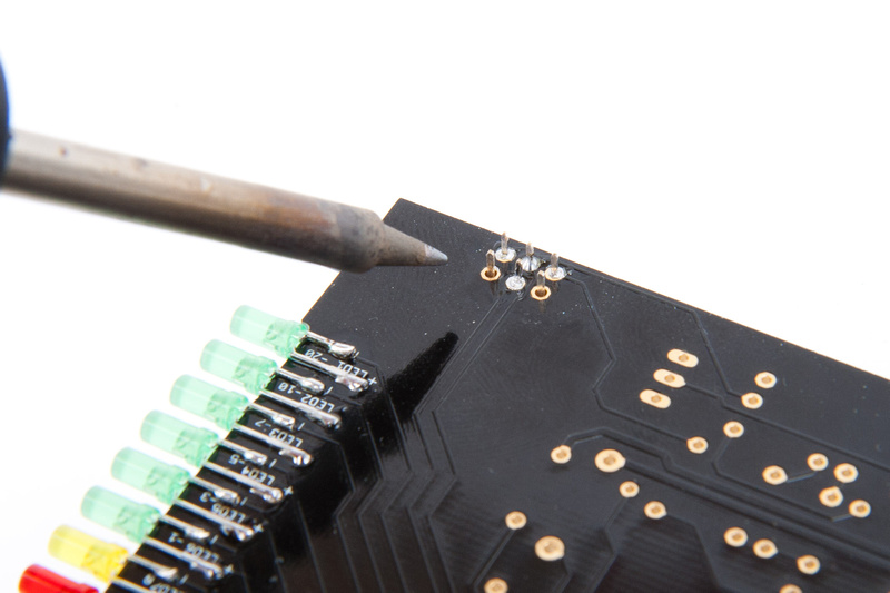
Next, I install LED's as clearly described in this thread by Igor.

p157719798-4.jpg


p499448393-4.jpg


p225500415-4.jpg


p114136824-4.jpg


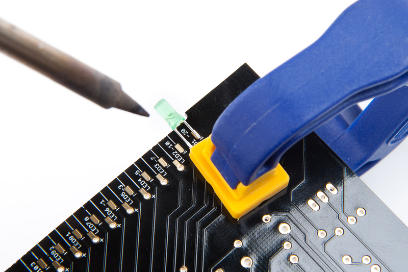
I used a clamp to help me position the end LED's for soldering.

p499484166-4.jpg


p305810698-4.jpg


p16767645-4.jpg


p215525386-4.jpg


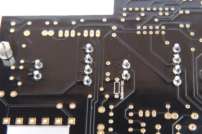
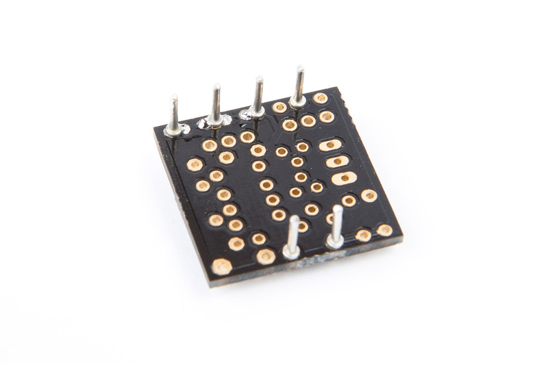
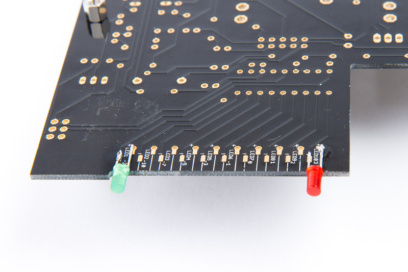
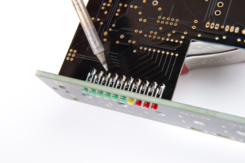
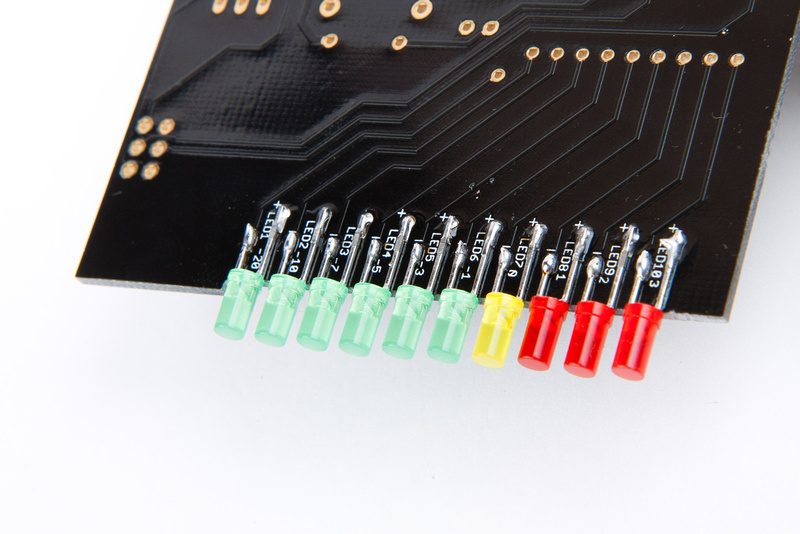
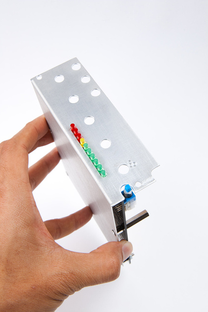
and, LED's installed.

p124391722-4.jpg


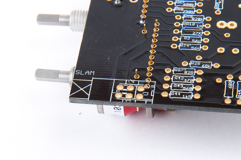
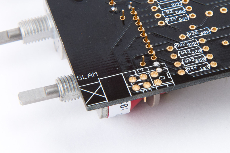
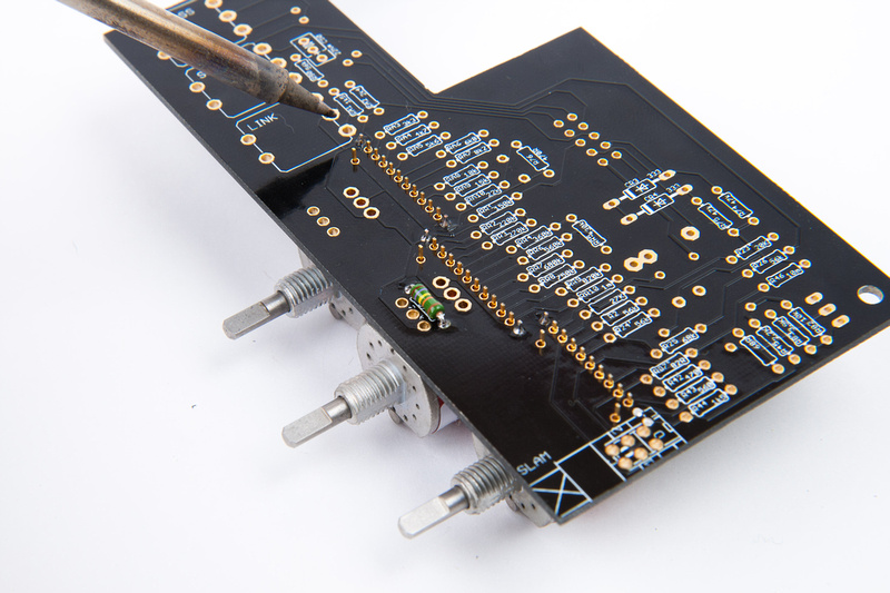
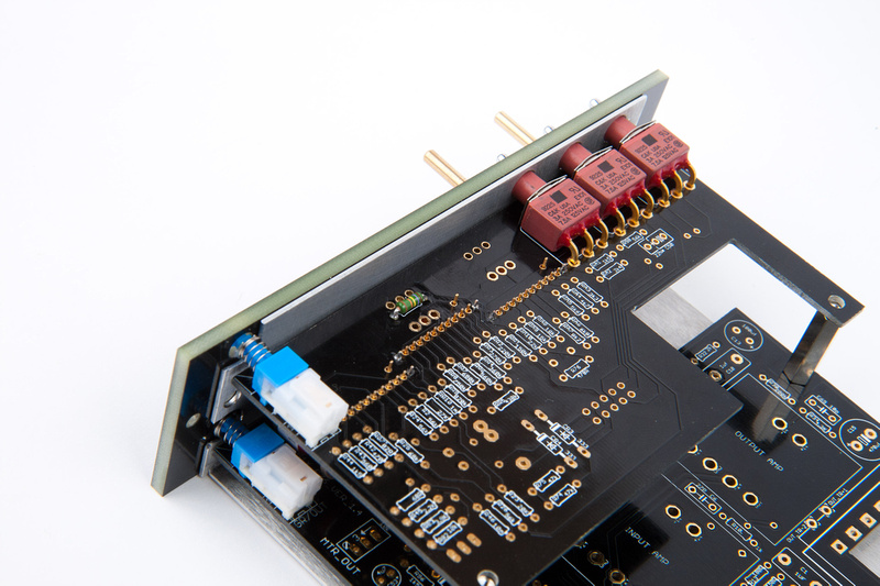
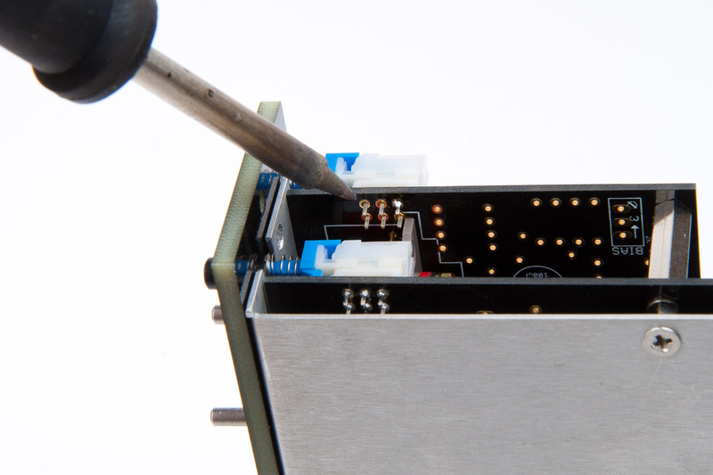
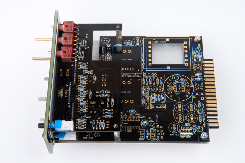
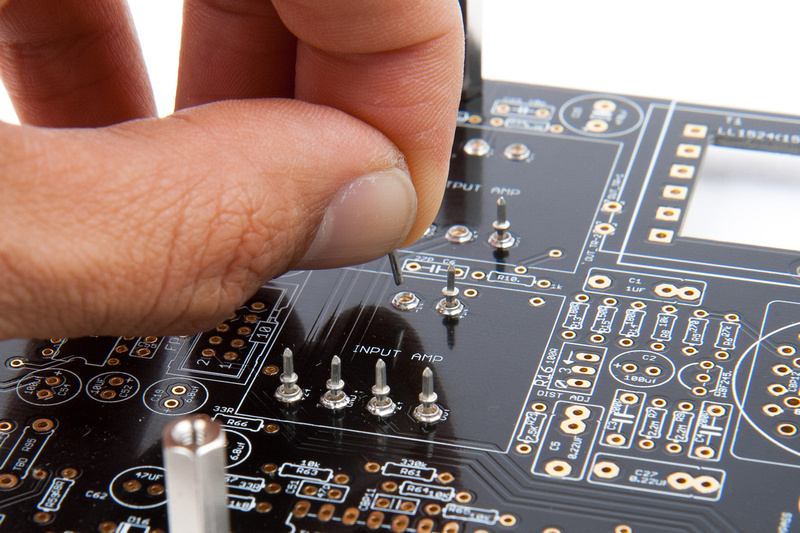
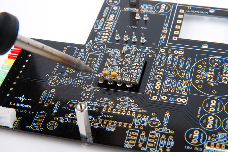
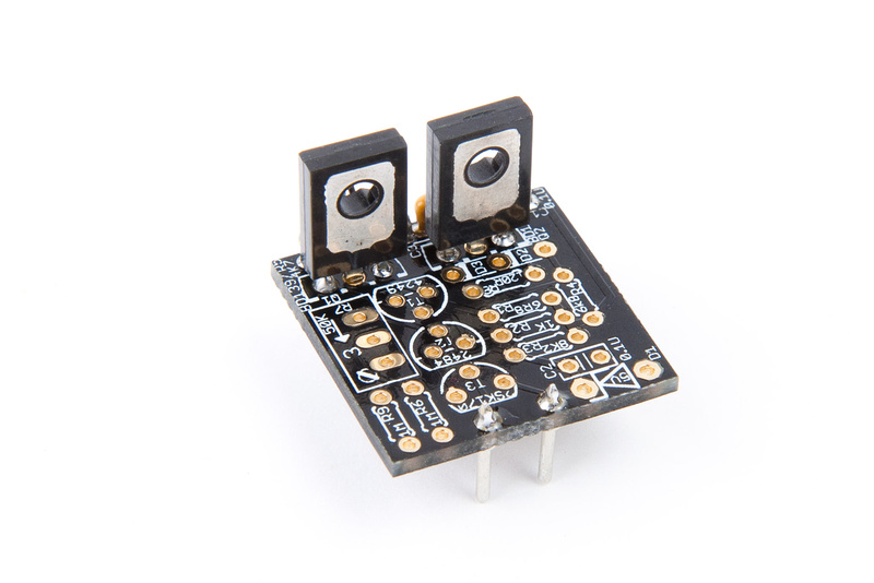
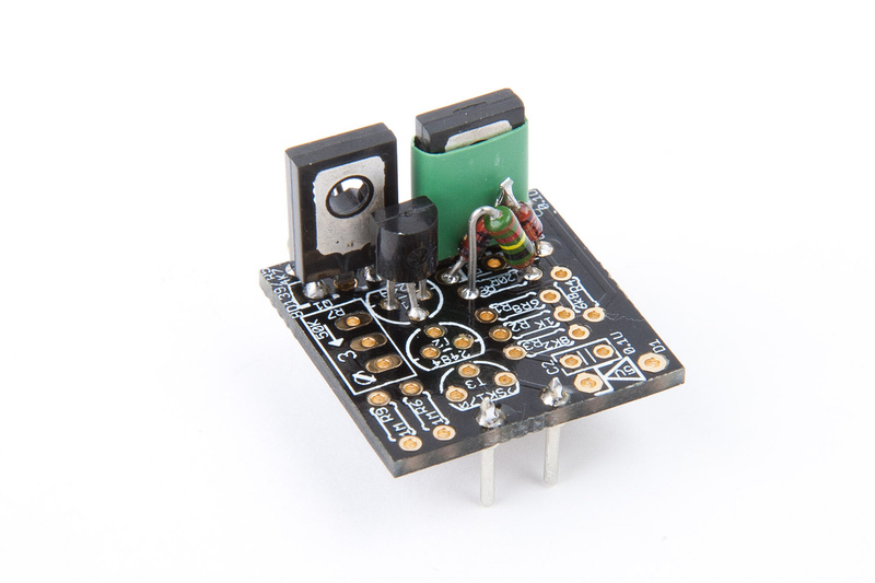
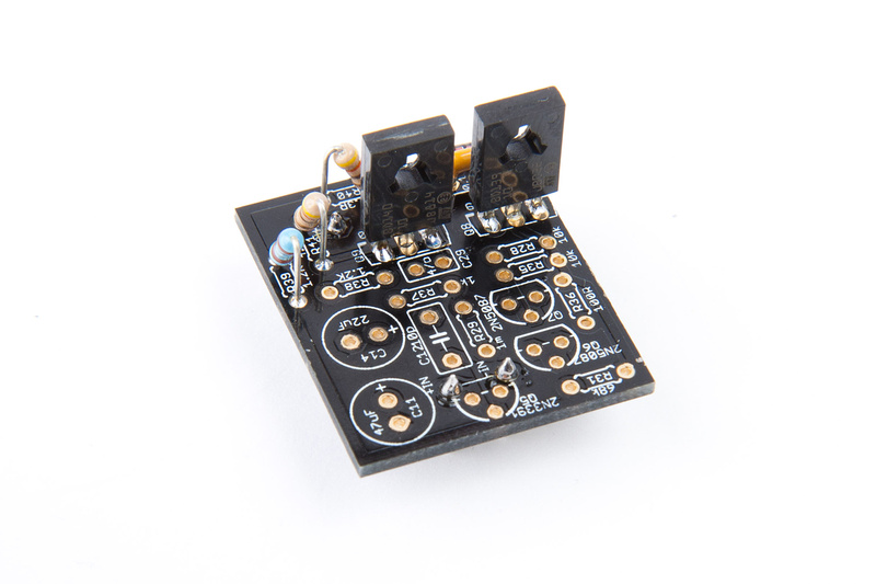
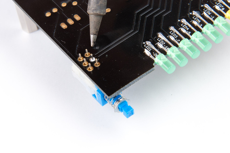
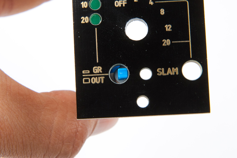
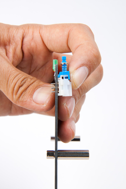
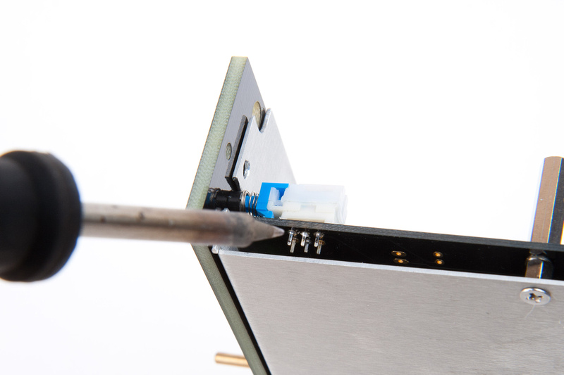
Next, I install my metering GR/output switch making sure to ONLY solder 1 pin.

p482826078-4.jpg


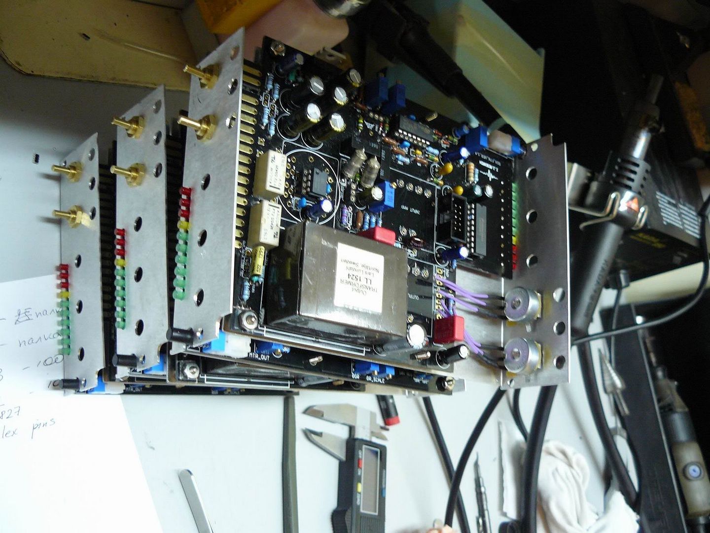
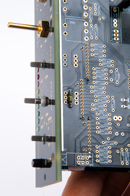
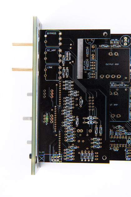
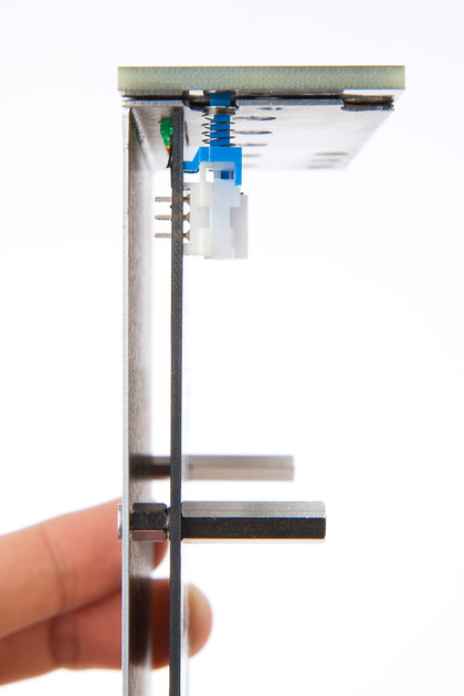
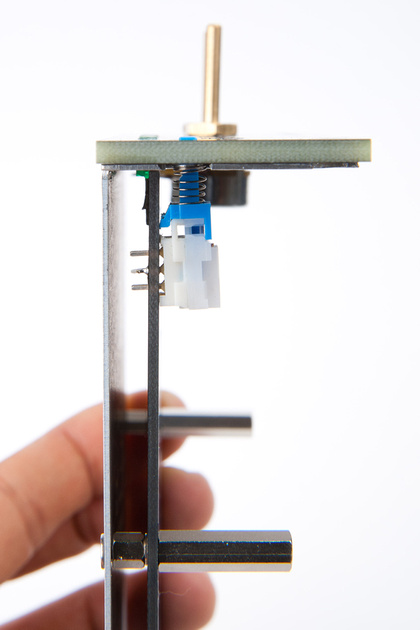
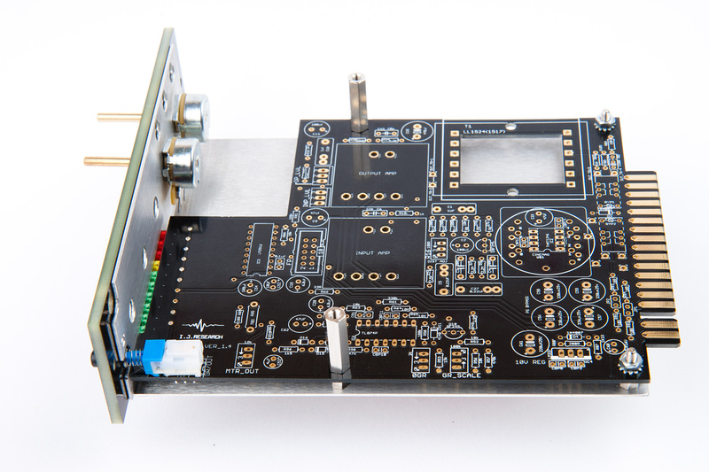
Then, I re-assemble to see how things are lining up.

p207708107-4.jpg


And, they are lining up poorly.

p36777157-4.jpg


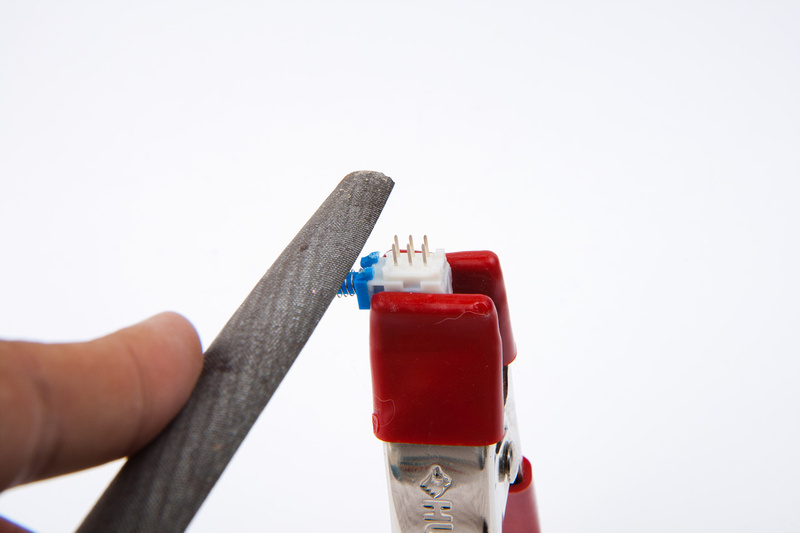
It seems the LED's are pushing the main PCB upwards a bit creating a bend, and causing the switch to move upward.  The LED's are all soldered in and I do not foresee them moving easily, so I decide to modify the switch to fit better.

p79998626-4.jpg


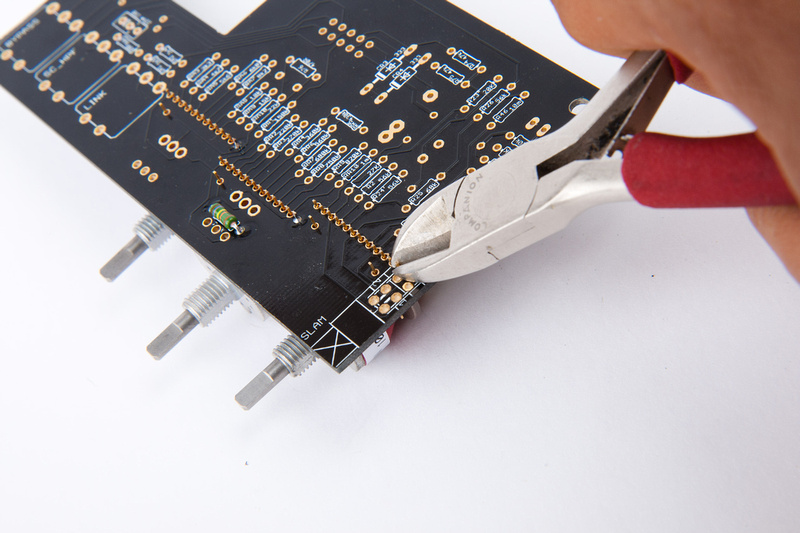
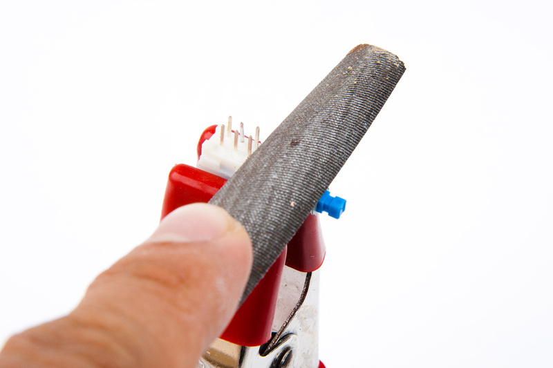
I figure I should try to compensate and make an adjustment so the switch is not installed under strain.  I remove the switch (luckily, I only soldered one lug) and file the front mounting tabs.

p54048014-4.jpg


now the switch will mount in a compensated position.

p321123961-4.jpg


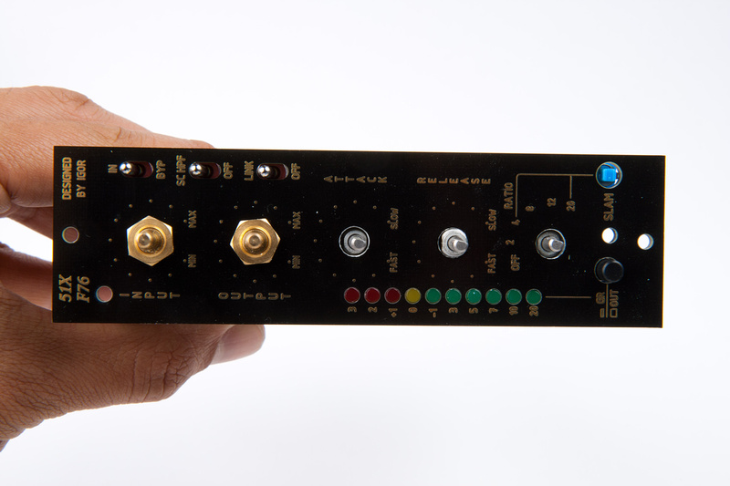
I re-mount soldering again, only one lug to verify.

p406719961-4.jpg


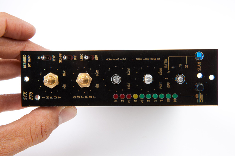
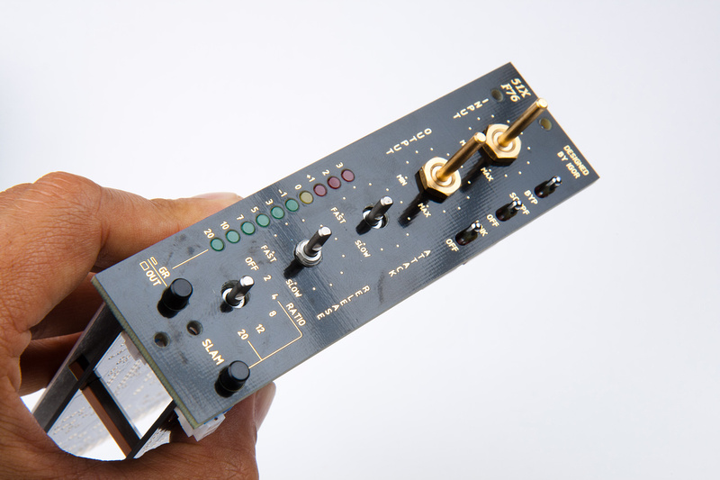
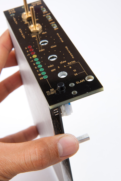
And, my alignment is now reasonable.

p256595250-4.jpg


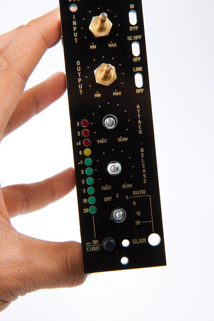
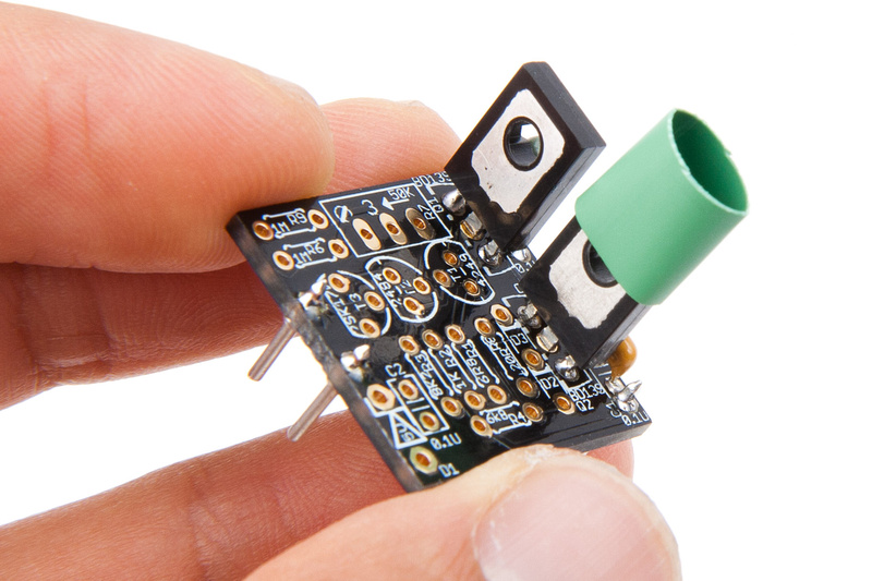
I install the external button to confirm

p287103817-4.jpg


And then, when I am satisfied that the switch position is good to go, I solder the 3 accessible lugs in place.

p39146212-4.jpg


Then, I disassemble and solder the remaining lugs.

p50582962-4.jpg


Here I am for now. . . slow, but steady gets the job done right I hope. . . next, I will align the grayhills on the upper PCB.

p438920479-4.jpg
 
Hey Chunger

I'm just checking, but you do know the nuts on the pots go on the aluminium bracket and so are hidden by the nice face plate right?  ;)
That's why there is a recess on the back of the faceplate...

look:
P1050913.jpg


Good luck with it

The Gimmer
 
Awesome. . . .no, I did not.  That's why there are "redundant" alignment/securing screws for the faceplate :)  Cool stuff.  I do not think the build has been adversely effected yet with the exception of a few scratches that will be covered by the knobs.
 
finished one of mine!  Not sure if I got the meter calibrated correctly but who gives a sh*t, check out this audio clip!!!

this is just an Apple drum loop.  Wait for the SLAM mode at the end!

http://www.zshare.net/download/96271568919bf8bd/
 
Igor.

Almost done [finally] with my 2 F76s

Question about R11'

Is this used with all input amps? I am planing to use your cascode amp. Is it also required with simple IC input amp [ AD7111 or OPA 604] and also 'original' version

Thanks

The Gimmer
 
some more progress tonight, and a bit of frustrations with this project. . . at this point in physical build, I wanted to move upward onto the chassis and place the control components of the attack/release/ratio board.  When I examined the board, one resistor would prove difficult to solder after the grayhill switches were installed, so I needed to go to this baggie and find R79 (270K).

p640351932-4.jpg


p682484593-4.jpg


After installing R79, I went ahead and installed the release and attack switches soldering only 1 lug for easy shifting or removal so I could verify physical alignment prior to soldering more.

p663912341-4.jpg


p554061871-4.jpg


per the instructions, the ratio grayhill switch needs to be trimmed on the 2 outer legs to allow the slam button to be installed.

p575007090-4.jpg


p636704127-4.jpg


p932036121-4.jpg


p556819182-4.jpg


And those 2 legs can now be soldered in pretty much flush to the PCB.

p1071458226-4.jpg


Verifying alignment of grahill switches attack, release, and ratio.  Looks good. so far.

p1000010916-4.jpg


The release switch along with the input/output pots will have to have their shafts cut at some point.

p1057581437-4.jpg


Verify the grayhill switches are flush to the PCB. . .

p710031447-4.jpg


. . . and I solder in 1 more lug on each switch to secure the back side flush to the PCB.

p575743270-4.jpg


Alignment is good still.

p984132183-4.jpg


Next I pull the switches for this board.

p1067803951-4.jpg


And position them on the chassis to see where I am in terms of alignment.

p610744174-4.jpg


Pretty good on the bypass, link, and HPF switches, but the slam switch is off a bit.

p636770013-4.jpg


So, i file a bit on the front standoffs. . .

p544937511-4.jpg


And, it looks much better here.

p806755546-4.jpg


. . . so I solder from the back side.

p593258842-4.jpg


Then, flip and solder the remaining lugs.

p392645684-4.jpg


Next I solder all of the accessible lugs (including grayhills) with the switches, faceplate, and chassis assembled.

p448269757-4.jpg


disassemble, flip and solder the remaining lugs.

p240812275-4.jpg


switches are all aligned and installed.

p469104561-4.jpg


p21527118-4.jpg


p523066949-4.jpg

 
OK. . . a few questions in this post.  I hope Igor can chime in and help a newbie out.

Next, I decided to stuff the attack/ratio/release board because I had it out, and was already digging through the resistors.  I discovered that there were several different brands/colors/types of resistors, and further, there were value substitutions in the kit.  For a seasoned electronics tech, this should not be a problem, but for a new builder like myself, this is problematic.

p403529918-4.jpg


After stuffing the board, I did not have confidence enough to solder the resistors in without verifying substitutions are correct and proper.  Also, I am attempting to build a stereo pair, so I wanted to confirm that my 2nd kit which due to packing mistake on the initial batch, arrived quite a few months later with different components and substitutions was not dramatically different.  I tried my best to shuffle resistors around between the 2 kits and match the values but have questions about some of the changes and differences.  To Igor's credit, a few of the substituted value resistors in the kit had enough spares included to cover another PCB.  I guess this problem was somewhat anticipated, but I still do not quite understand why so many substitutions.  I need to find out if I will have to order some more parts to get the values closer, or if this is all ok, and I can solder these parts in.

p190395815-4.jpg


R25 (68K) on the ratio switch . . . one kit has 67.8K and the other kit has 68.8K.  Will this offset the 2 units drastically?

R74 and R75 (47K) on the detector. . . the closest resistors I found were 2x 47.5K and 2x 46.5K . I put 47.5K into the first kit and 46.5K in the second kit because the schematic looked like these resistors may need to balance within the circuit.  Will these alterations in the detector portion make sonic differences between the 2 units?

RA9 (15K) one kit has 14.69K and the other 15.05K

R42 (470R) was substituted 464R in both kits.  . . any problems with this?

R76 (470R) was substituted 462R and  464R . . . any problems here?

R79 (270K) the kit supplied these as 274K, but I am missing one.  Kit cannot be completed without.
p120121375-4.jpg


Should I re-order any of these resistors to find closer matches?  or is it ok to solder?  I will wait until confirmation before sticking these components together :)

This is a bit frustrating for me chasing values around the documentation instead of moving forward with assembly.

p216356921-4.jpg


Hey Chunger.

I had the same thing, but in my case I had a lot of resistors from previous projects so I was mostly covered where I wanted to have closer values between 2 kits.

I'm no expert but I would say remember this:
These are 1% resistors but the original 1176s would have been built with 5 or 10% tolerances, so don't sweat it too much. For example your RA9, one is 14.69K and the other 15.05K. The 14.69 is only just outside 1% the other well inside.
OTOH I agree that when building a stereo pair it's good to match channels as closely as possible, (but then e.g. for attack and release and side chain circuit  you'd also want to match caps values closely too.)
Resistors are cheap and you could always just buy the values that you think are too far off.

Hopefully Igor will chime in here. I still have a question regarding R11'


Question about R11'

Is this used with all input amps? I am planing to use your cascode amp. Is it also required with simple IC input amp [ AD7111 or OPA 604] and also 'original' version


Igor?


The Gimmer
 
Ok. . . waiting still on replies about resistor quiestions and waiting to see if I should put in an order to get the pair to match a bit better.

I thought an input amp build might cheer me up a bit. . . (correction from previous). . . please note, parts are only provided for 1 input amp and 1 output amp option.

I figure I'll start with the Igor's input amp.

To decided to start by putting the Mil Max sockets in.  Your methods may be different and better, but this way got the job done.

p300419462-4.jpg


I was hoping with the little ridges on the sides that there would be some sort of friction fit on these to hold them in place for soldering because I was afraid to get solder on the inside of the sockets and have them seize up, but these are very small and very loose, so my plan of attack changed to soldering these in from the bottom and hoping gravity would keep the solder from flowing up into the sockets.

p92109700-4.jpg


I had to re-heat and press down on the sockets to make them seat properly, but it seems everything worked out ok.

p60636152-4.jpg


p8216326-4.jpg


Then, I inserted the milmax pins so I could have them aligned nice and straight when I solder them to the amp PCB.

p352081437-4.jpg


AMPS-BAG3 contains the components for Igor's input amp. . . I hope.

p532071389-4.jpg


The holes for C1 and C3 were very close to the milmax pins, so I thought I should insert them prior to soldering the pins just in case I got solder overflow and ended up plugging up the holes and making a mess.

p519549203-4.jpg


And, this is how I solder on the pins.

p243974049-4.jpg


I did have to clean up the solder joints for the capacitors from the bottom, and I probably didn't have to install them at the same time with the pins, but better safe than sorry, eh?

p295657644-4.jpg


And, we're populating.

p163509580-4.jpg


p469403630-4.jpg


A little piece of heat shrink tubing over Q2 helps to keep D2 and D3 from shorting against the metal part.

p183612587-4.jpg


D2 and D3 are marked like this:
p527446841-3.jpg


p154267866-4.jpg


p324208607-4.jpg


p30729045-4.jpg


p101842917-4.jpg


p158606340-4.jpg


p219543567-4.jpg


p45074195-4.jpg


D1 has the following markings:
p358896757-3.jpg


p230097320-3.jpg


p41651933-3.jpg


p225982379-4.jpg


And that completes this input amp.  There is a modification that Igor suggests for "tasty sound" that I may try on this amp as well, so I should put that resistor on my shopping list, but for now. . .

p178775160-4.jpg


p301078389-4.jpg


Found another missing part in my kits. . . in AMPS-BAG2:

2N5087 937 found possible replacements at Mouser. . . 2N5087TA, 2N5087TF, and 2N5087BU. . . checking to see if any of these will work.

Note to self:

Original output amp (AMPS-BAG2) "steals" the following components from (AMPS-BAG1. . . the IC output amp bag):

1x 10p ceramic capacitor (10J)
1x .1u ceramic capacitor (104)
1x BD140 transistor
1x BD139 transistor

if building all amp options, these components along with extra Mil-max pins will have to be purchased.
 
On to output amp. . . I chose to build the "original" amp. . . largely because I do not own a vintage or clone 1176 and wanted to hear what the original was all about. . . distortion and all.  My gut feeling is the IC output amp may give better sonics, but I have a pair of APP2520E that can run on +-24V.  In the original application (VP312DI), preferred the GAR2520, so I can use these in the f76 builds if I like them.  My plan is to order parts to build all amps in this kit and hear them.  Contacted Igor about his Albatross op-amp that he prefers as well.  Options. . . no point having them if you can't hear them for yourself  ::)

For this step, I refer to the following files in the documentation:

orig_outamp.txt  (component list)
orig_outamp.png  (schematic)
orig_outamp.gif  (PCB top view graphic)

First, I use the main PCB to align the Milmax pins and solder in this position.

p413287209-4.jpg


p289703671-4.jpg


Most of the components for the "orginal" output amp are found in AMPS-BAG2.

p479875032-4.jpg


And, I begin populating the board:

p201238773-4.jpg


Note: in the next step, CBP23 (.1uf marked 104) is taken from AMPS-BAG1.

p229779134-4.jpg


Note: in the next step, Q8 (BD139) and Q9 (BD140) are taken from AMPS-BAG1.

p243833586-4.jpg


p441607123-4.jpg


p428471118-4.jpg


p459634179-4.jpg


Note: in the next step, C12 (10p marked "10J") is taken from AMPS-BAG1.

p425525220-4.jpg


p413392673-4.jpg


And, the "original" output amp option is complete.

p202532284-4.jpg


p6964729-4.jpg

 
Tried to make some more progress on the build, but have a quick question before I move forward and post erroneous photos.  I can't seem to be getting fast replies from Igor. . .

2  200PF        5 OR 7.5MM <>      C3, C4

These are the silver/clear weird-looking capacitors.  The 2 that I have in one of the kits are marked "220J":

p660435656-4.jpg


this indicates to me 22pF which would be quite far off from 220pF which would have been a substitute value?  I believe this capacitor may be incorrect and do not want to proceed with posting step-wise build progression photos until I can confirm.

p1003810999-4.jpg


yes, those are the 200pF.  Think of the designation as:  2, 2 zeroes.  and then J means PF, i guess.    Wima kinda uses the same format.    xy, where x is the Most Significant digit and then y is the number of zeroes.

If you look at igor's assembly pics, you'll see those same capacitors used in that location.
 
does anyone have any ideas as to what would cause the meter to go backwards?    I finally got my 2nd unit fully assembled and the first unit's meter started behaving backwards after I started tweaking the bias dial.    I am confused...

edit:

Nevermind, got it figured out.  if you crank the GR_SCALE too much, the meter will run backwards for whatever reason.    Both units are dialed in now!!!

Could someone explain what the Link switch does?    Does it cause both units to run off of the average of the two channels? 
 

Latest posts

Back
Top