mulletchuck
Well-known member
I found this little site which really helped for converting between Vrms and dbU and other units.
http://www.sengpielaudio.com/calculator-db-volt.htm
http://www.sengpielaudio.com/calculator-db-volt.htm


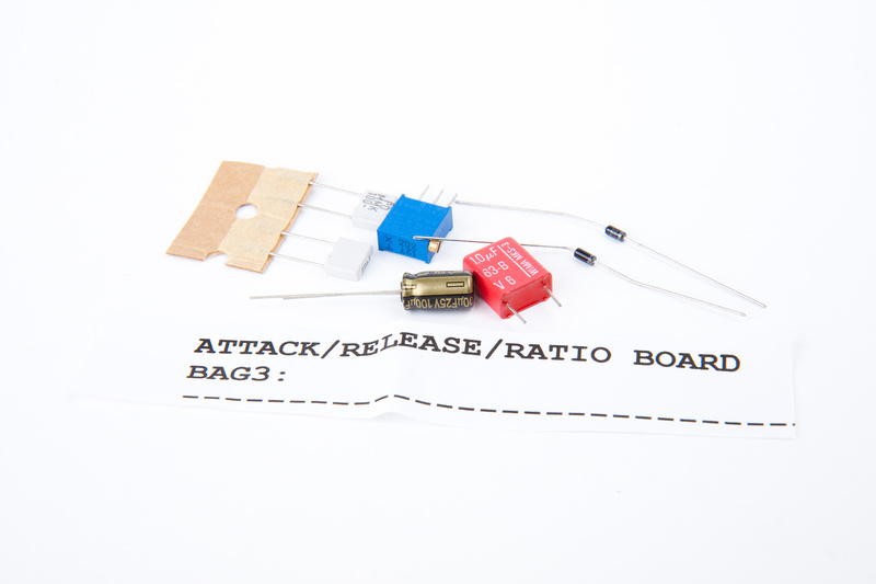

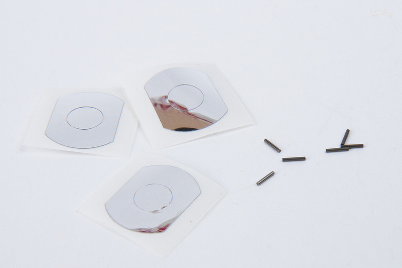
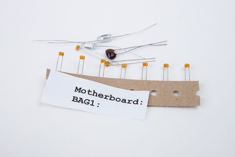
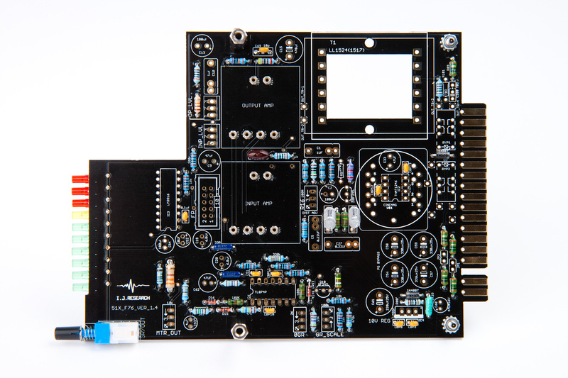
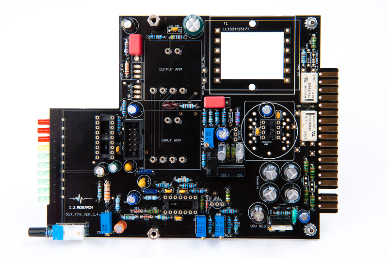
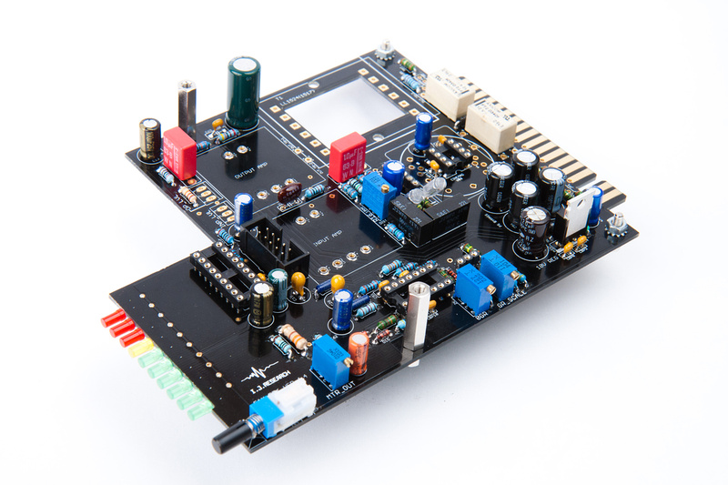
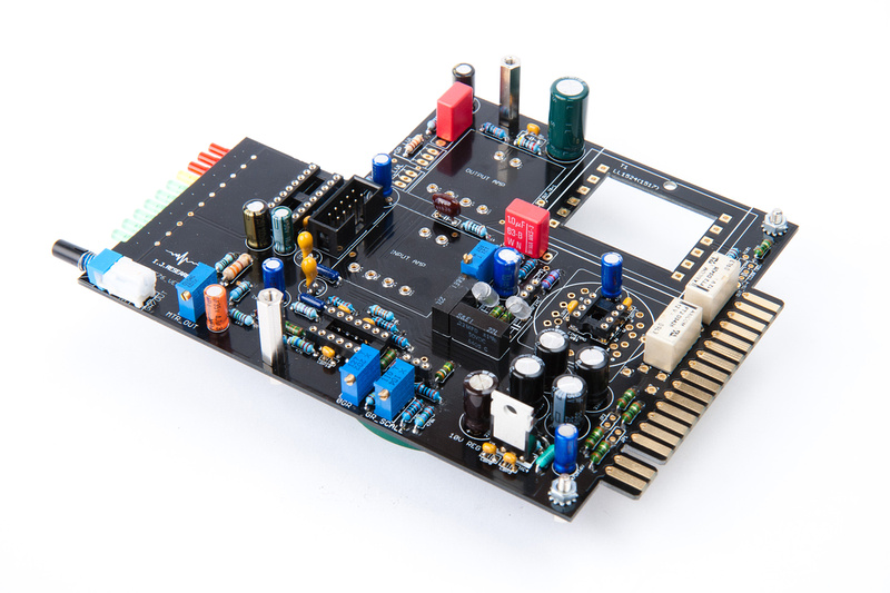
mulletchuck said:I just wanted to point out to anyone who recently bought this kit. DO NOT throw out the unlabeled parts of the PCB that are in this picture:
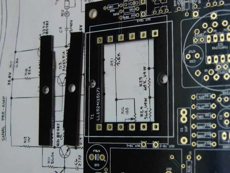
They're spacers for when you mount your transformer. I didn't know this, and they are somewhere in a New York State garbage dump or recycling facility because they weren't labeled or explained.


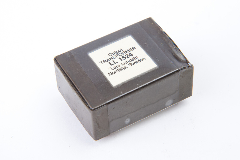
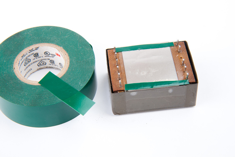
andre tchmil said:@ andre tchmil do you have 2 1524 output trannies available still? I'd take 'em
sure how many kilograms do you need ? ;D
email me for ordering, thanks
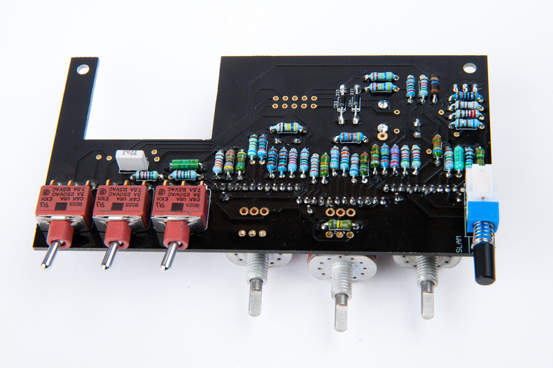
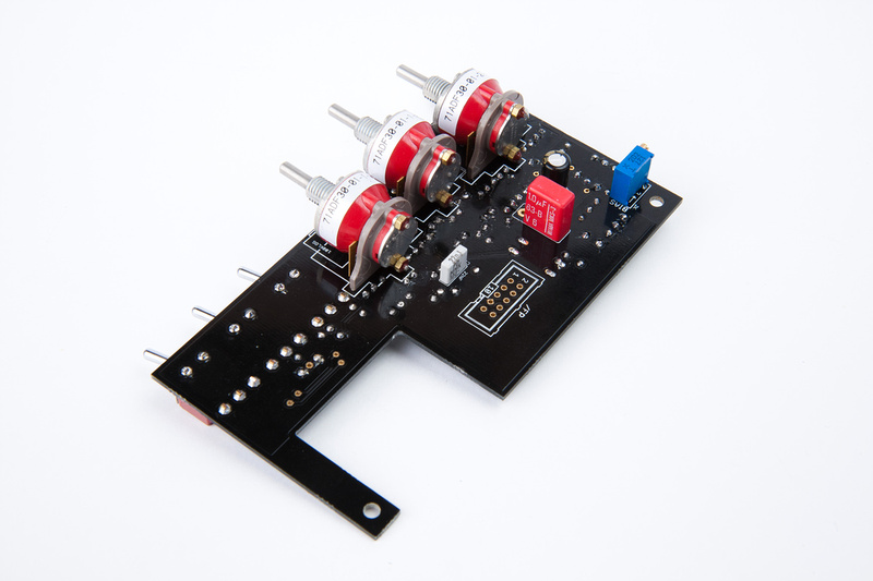
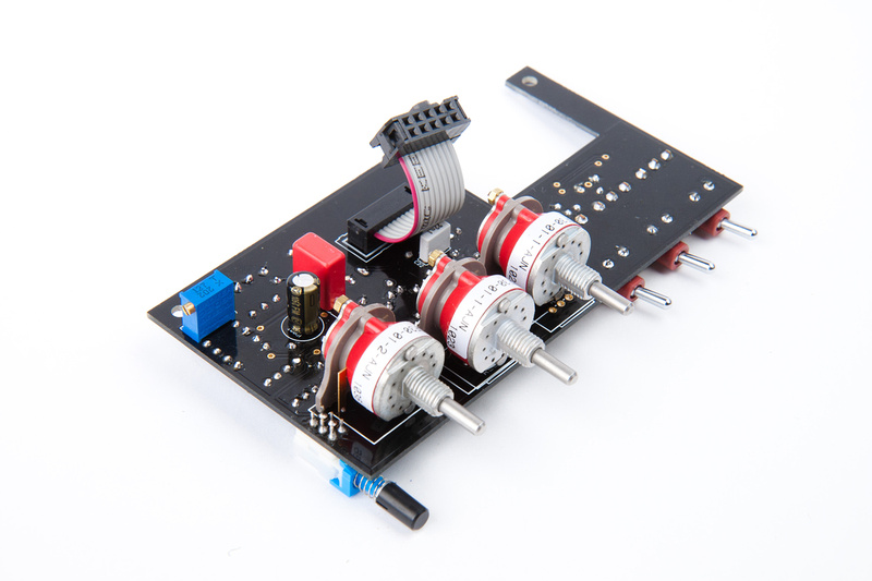
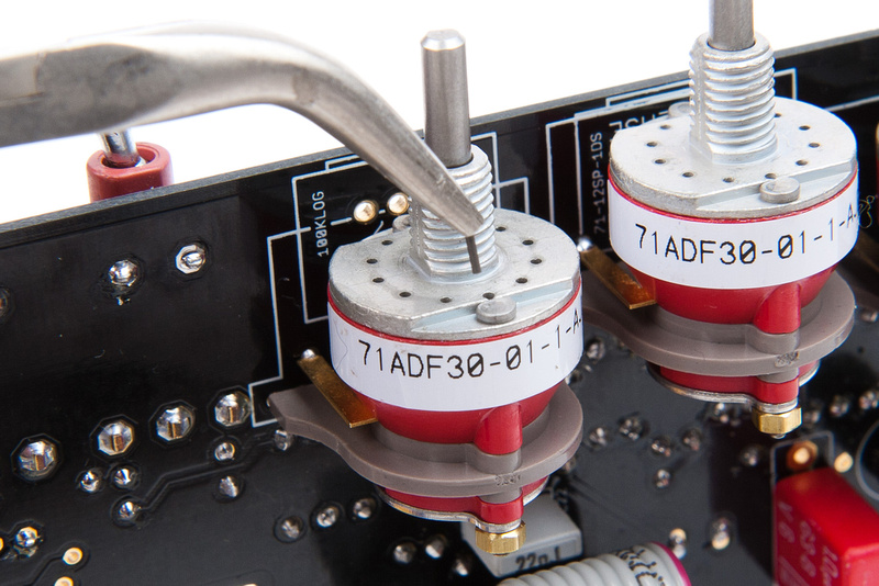
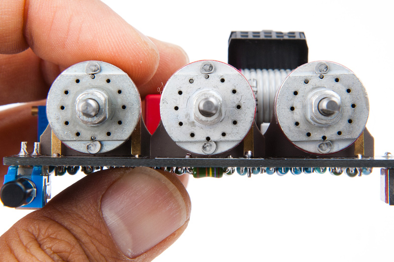
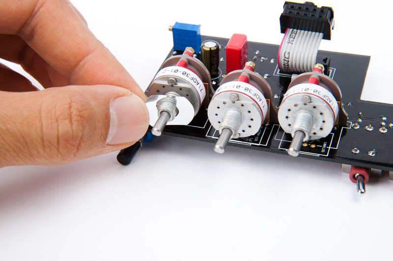
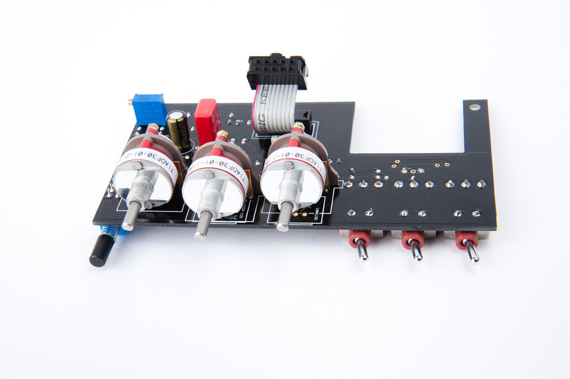
- The Attack and Ratio Grayhills didn´t expose enough shaft for the knobs that I chose. Fortunately I could mill away a millimeter from the metal knobs. If you can´t do that pay attention to the dimensions when choosing knobs.

Enter your email address to join:
