1176 in 51x/500 format, or 51X-F76 Build Support Thread

GroupDIY Audio Forum

Help Support GroupDIY Audio Forum:

This site may earn a commission from merchant affiliate links, including eBay, Amazon, and others.
It's those:

6.35mm
http://search.digikey.com/us/en/products/OEJL-63-2-5/226-1089-ND/710652

3.17mm
http://search.digikey.com/us/en/products/OEJL-63-2-6/226-1085-ND/710656

So as said, you need to trim the bottom, AND also trim the grahill shaft, because the screw is landing on the sharp side and not
on the back of the D, Plus trim a little the inner screw tip to make it seat flat on the trimmed shaft.
A little expensive considering all the extra you have to do to make them fit..
But those Elma's were too tiny for my fingers and those Grayhills.

I didn't bother trimming the Input and Output ones...

I went T Pad & transformer input too. Did you use Igor's DOA [ the one that's like an eye test to build! ]

No i went Original Amps, but i builded all of them, so i'll try it out...
 
901 said:
Just wanted to let you guys know: I have finished mine after all!

There are a few things I had hassles with and maybe this info is of good use for others as well.

- as stated earlier I had difficulties sourcing 2N4249 and 2N4250A. I managed to get my hands on two 2N4248 though. The BOM mentions these as the primary parts to get with the PNxxxx types as exchangle. The 2Nxxxx have metal housing, th PNxxxx are plastic. I would like to advise heavily AGAINST the 2N types since they all so easily touch other parts on the heavily stuffed DOAs and cause shorts! And they are larger, too.

- The LEDs don´t line up well with the cut-out in the metal bracket and front causing a little tension on the motherboard. If I had to do it again I would try to place them not so tight against the board so that the pins get gently bent rather than the board itself.

- The Attack and Ratio Grayhills didn´t expose enough shaft for the knobs that I chose. Fortunately I could mill away a millimeter from the metal knobs. If you can´t do that pay attention to the dimensions when choosing knobs.

- For some reason I had difficulties to get buttons for the push switches. I´m currently using an interim solution by abusing the heads of two M4 hex screws. I think it´s funny...  8)

After adjusting everything I just toyed around with it a little and this thing is really fun! Even if my points from above may sound like trouble, it was fun to build and absolutely worth the effort.

Unfortunately I have never used a real Urei 1176, so I cannot compare. But I don´t care for originality. I think Igor made an excellent job on this one!

Congrats 901 and thanx for feedback!!!
The buttons for push switch are available on DigiKey, check the BOM for P/N's.
Soldering LED's is bit tricky, but I did it with about 20 compressors.... and it worked.
Knobs: my favorite is ELMA. They have virtually any shaft/size variations. I cut Grayhill shafts with Dremel tool and cut-off discs.
 
Sorry about the extended delay. . . a few other projects came creeping in, but I'm starting to make some more headway on these f76 builds.

I had a misunderstanding about the nut locations on these, but I think I've got it now.  The nuts for the pots and grayhill switches seat underneath the faceplate in the machined recesses.  So, there are a couple of threaded inserts and hex screws that hold the faceplate on.  These did not readily fit into the holes completely.  Since the location would be very difficult to tighten, I figured I'd just try and press them in.

p24762661-4.jpg


p285187313-4.jpg


p256016805-4.jpg


Boom. . . works like a charm.

p425177560-4.jpg


Next my Zobel network resistor and cap.  R101 and C100.  As I understand it, the higher value resistor and lower value the cap, the less treble attenuation will happen, so I went with those ends of the recommended range.

R101 469R
C100 4.7nf

p75873719-4.jpg


The cap I ordered is wider than the PCB was designed for, so it did not fit very cleanly, but I think this should hold up ok.  I really don't feel like delaying this project anymore.

p291844666-4.jpg


p504953775-4.jpg


p115044516-4.jpg


Next, I soldered a few leads onto the input and output pots.

p204196256-4.jpg


and connect to the PCB. . . please let me know if the leads aren't properly connected.  This is how I decided to go after looking at the schematic a little, but unfortunately, I don't know how to read schematics, so there you have it.  That's how confident I am  :-\

p72355395-4.jpg


Next, per the build instructions in the 1st 2 posts, I connect my link lead just in case I use this as linked pair.. .

p68850546-4.jpg


And, it looks like I'm ready to apply power and do my 1st round of voltage checks.

p522147486-4.jpg


Ran into some problems w/ my input amp upon initial testing . . . hopefully Igor can help me find the cause.

Ok. . . hooking the F76 up to my testing power supply which is JLM powerstation.

p353874247-4.jpg


No smoke!  Humans win!

Checking voltage at LM337.  I am looking for -10v here according to test procedure.  I guess -9.7 isn't too bad?

p364082322-4.jpg


While I'm here, I might as well poke around a few of the other power points and check to make sure amps will be happy.

p416112168-4.jpg


p346664361-4.jpg


Installing test jumper

p153731691-4.jpg


Installing main PCB IC's

p270145074-4.jpg


p288229664-4.jpg


p510292872-4.jpg


p156733251-4.jpg


Output amp goes in.

p8924691-4.jpg


Input amp goes in.

p376260130-4.jpg


p65479305-4.jpg


And, here's my problem.  Test procedures say with input and output pots closed,  I should adjust the input amp's trim pot to read .3V - 1V with a volt meter between the amps output and ground.  At the end of the trim pot's adjustment range, I can only get it down to 11.6V which is wildly out of range.  So, I'll stop here and see if anyone can take a look at my build progression photos on the input amp and spot a component error. . . or if i wired my input/output pots wrong.

p227400165-4.jpg


UPDATE:  Found the problem.  There was a faulty BD139 on Q1.  With faulty part replaced, input amp trims out within spec.
 
for that last step, you don't have the GR/Audio transistors installed.  Does that make a difference?  I remember having a similar problem with mine, i just had to keep turning and turning the trimpot and eventually it worked.    i mean, turning it both directions the whole range.  it was not intuitive.
 
test procedure is saying not to install audio and GR transistors yet. . . I messed with it again, and now the range is 23V-9V.  Still out of range.  I double checked my photos for the resistor values installed on the amp via photos, and those look to be ok.

Chuck, do my input/output pots look wired correctly?
 
yes they do.  Also, I tested my amps between the GND pin on the amp, not the GND pin on the 51x connector.  Not sure if it makes a difference...  one would think that they are part of the same GND circuit....    But i know nothing lol.    You might want to hit up igor on FB, cuz he's posting a lot of pics recently.
 
Igor says he'll be back from vacation tomorrow.  In the meantime I attempted to build from my 2nd kit Igor's input amp to test.  I have awesome pictures, but unfortunately, I reversed D2 and D3 1N4148 like an idiot, so I got white smoke. . . and I can't post the pictures because I don't want anyone repeating that adventure.  Since I was looking right at the amp when I flipped the power on and shut it down in ~2 seconds, I'm hoping the damage is isolated to those parts.

Oh well, a trip to the electronics store tomorrow is in order.  I also recorded all actual resistor values when building this one looking for discrepancies that could cause my voltage woes, and noticed that R6 and R9 (R6 6 being adjacent to the trimmer pot) have substitute values. . . 909K instead of 1M indicated on schematic.  I'll pick up a pair of 1M resistors as well when I'm at the store and see if that gets me closer to where I need to be.  Guess that's a 9.1% difference though.  Probably insignificant but that's the only quirk I found.

Once more the Hakko 808 is saving my butt.  Pulling out D2 and D3 on a built PCB would have been tough without it.
 
I am finally getting around to building my F76. As this one will go into the portable rig in my API lunchbox, there won't be any +-24V which whittles down the options.
I am starting off with the most basic setup:
INPUT LINE RECEIVER -> IC INPUT AMP -> IC OUTPUT AMP - > B11148

Questions:
-Does the B11148 need termination and a zobel network? There are conflicting messages in the other 1176 threads (and nothing in this one).

-I have two pairs of very well-matched B245A's and the pairs match each other fairly closely. Should the very close matches go into the signal paths of the left and right channels respectively, or into the signal and meter paths of a single unit?

Thanks for all the tips so far and the mechanical gotchas.

 
progress and problems today. . .

First, I needed to repair the 2nd Igor Cascode-type input amp that I smoked last night.  Luckily, I have an electronics store local that actually has parts in stock.  Hakko 808 to the rescue.

p885747333-4.jpg


Since I had my de-soldering tool handy, I decided to replace the 901K R6 and R9 resistors on the 1st (mis-behaving) amp to see if that resolves my problems with it.

p891053713-4.jpg


The bad news is the 1st input amp is still not showing the correct output voltage.  It is now ~16 volts with the trim pot bottomed out.  The good news is, the 2nd unit is working within spec.

p948212295-4.jpg


It's trim pot is also bottomed out, but it's reading within the .3-1 volt range.

Next, I took out a whole bunch of tools I have no idea how to use.

p736896891-4.jpg


My friend let me borrow a function generator and a scope that didn't have a probe. . . the electronics store luckily had a probe at a not-to-astronomical price, so I was in business.  So, these tools are now on semi-permanent loan since my friend seldom uses them anymore and they were in his storage unit.

p1068334890-4.jpg


p718695195-4.jpg


Since the F76 is balanced in and balanced out, I figured I should inject balanced signal, so I'm using my direct box which is of the IC opamp variety.

p794098659-4.jpg


the setup on my table for starting to test.

p584061618-4.jpg


ok. . . after pushing buttons like monkey on the scope, I think I finally figured out how to do some things with it.  Please keep in mind, I've never used a scope in my life, so all this is very new to me.

First test was to input a .01v RMS (-37.78 dBu) signal into the f76.  Here I'm using a 1K sine.

p591257097-4.jpg


And check output for ~37db undistorted gain.  Here, I have 3.32v RMS (12.64 dBu) output w/ input and output pots both at maximum.

p643726568-4.jpg


OK. . . please note here that I have another problem. . . My pin 3 and pin 2 outputs on the f76 are off by a large amount.  Pin 3 output is 8.78db lower than pin2.  I'm wondering if this indicates my output transformer is defective?  It is evident in the photos that there is significant physical damage to the casing, but I assumed Andre had tested these before they shipped.  The above reading is off of pin 3 (the low output one).

Taking into account the problems, I continue testing.  I insert 1v RMS signal.

p796124400-4.jpg


and max undistorted output on pin 3 is 10.2v (22.38 dBu)  minimum of 24dB is Igor's spec.

p1025698932-4.jpg


max undistorted output on pin 2 is 28v (31.16 dBu)

p625780664-4.jpg


and, another view of the pin 3 output which is low.

p177344079-4.jpg


ok. . . problems aside, I move forward.  I adjust input/output pots to output 1.23v RMS.

p295115594-4.jpg


and adjust trim pot until yellow light is solid on the meter.  The GR switch is in the "out" position.

p35178407-4.jpg


That's all for now. . . Questions for Igor:

1.  What is my next step to diagnose the malfunctioning input amp that is giving me ~16v at output?

2.  Do I have a defective output transformer that is giving me weak output on pin 3?

EDIT:

question #1 concerning the malfunctioning IJ Cascode input amp is still a mystery to me.  I went chasing around the schematic and PCB today with a patient and helpful friend on the phone trying to figure it out.  Pulled the 50K trim pot. . . tested ok. . . re-installed it.  Replaced Q2, T3. . . no change. . . Replaced C1, C3 mostly to make sure solders were all solid around the -24v area.  Still no luck.  This tiny amp is kicking my @ss.  Very frustrating.

question #2 Jeff from CAPI helped with.  It's more of a common knowledge answer that I simply was unaware of.  Many output transformers do not have a ground reference, so they are floating ground.  The + and - side of output will not necessarily reference to ground equally so the offset I am seeing on the scope is normal.  I decided to calibrate 0 dB with a sound meter w/ a balanced input, and when I connected a load, the + and - sides evened up significantly on the scope.  The output transformer is fine.  Verified by pulling the output transformer and replacing it w/ same behaviors.
 
Have run into a bit of trouble with my build....voltages are fine without the amps and chips,
but as soon as I drop in my IC OutAmp Resistors R93 and R94 start smoking, before I even get a chance to measure the voltage across them. I am using slightly different Transistors:
PN2484 instead of 2N2484, as Farnell don't carry the latter.
My version of the 2N4250A is a bit different as well, it comes in a metal container.
I checked PNP and NPN and pinouts on datasheets and with the hfe function of my meter - everything in order.
with the IC OutAmp inserted, I still have normal readings across the voltage rails (-16 to Gnd, Gnd to +16), around 1k Ohm and rising as the PSU caps charge.
Any ideas anyone?
 
ok. . . one more push to finish up this build.

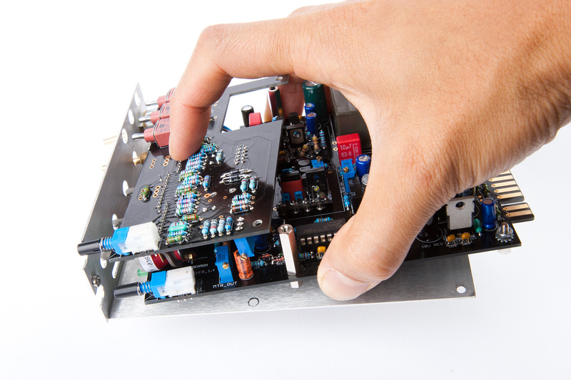
Please note, this step is pre-mature, so I will have to take out the audio and GR fets for a calibration in the following steps, but this is when I put them in, so here are the pics.
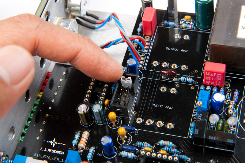
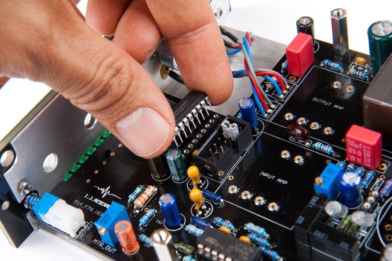
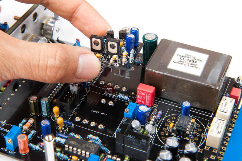
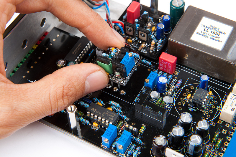
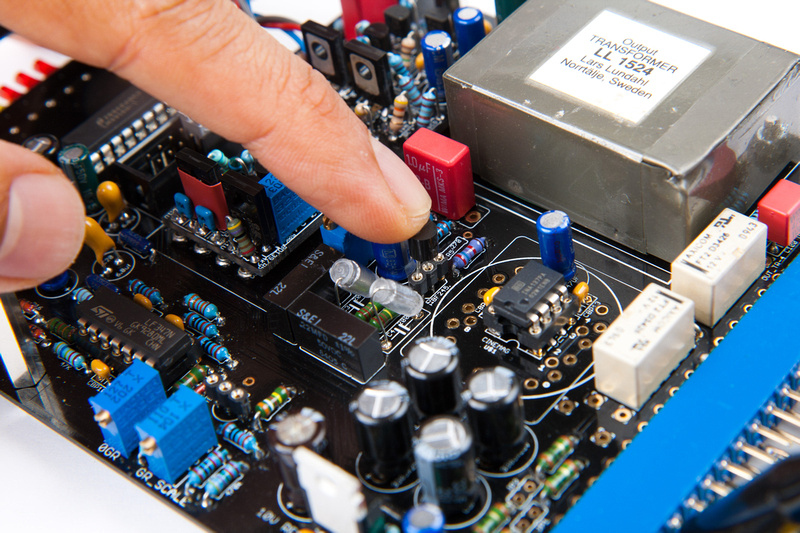
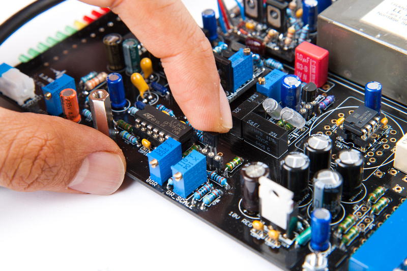
Audio FET here:

p346493286-4.jpg


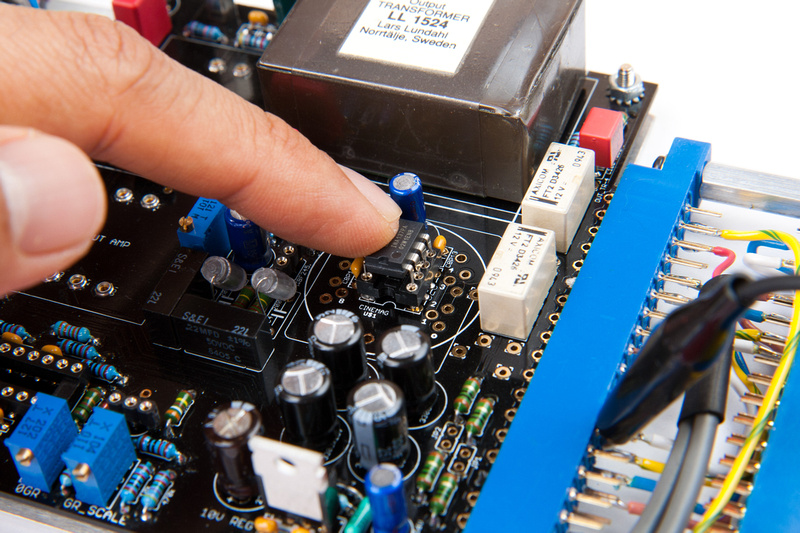
Gain Reduction FET here:

p282120568-4.jpg


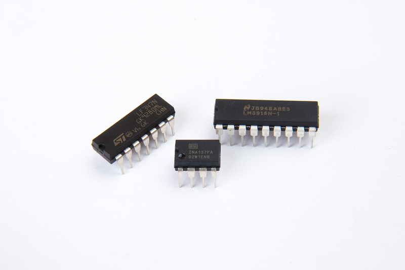
Note these are matched pairs provided in the kits and they are different than original spec FETs so these insert reverse direction from the indicated markings on the PCB.

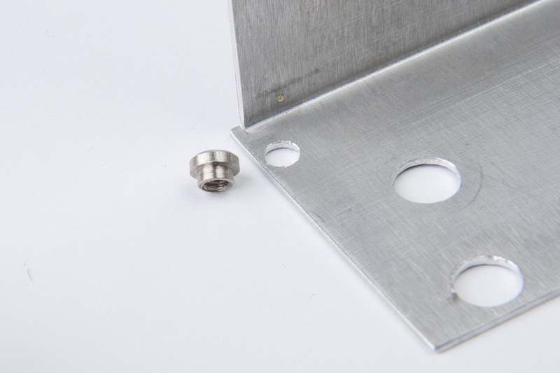
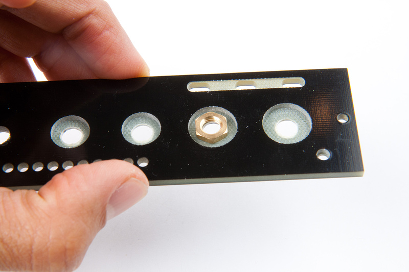
NExt, I address a mechanical fit issue I noticed when rough assembling the module.

p160579574-4.jpg


This nut is too thick to seat fully into the recess provided in the front panel, so we will have to thin it a bit.

p162716615-4.jpg


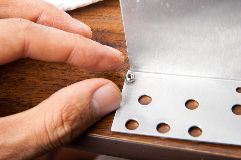
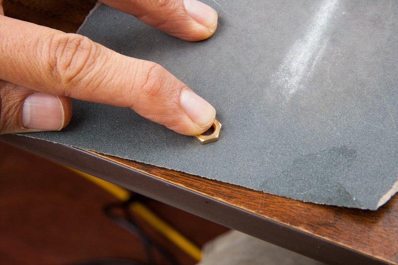
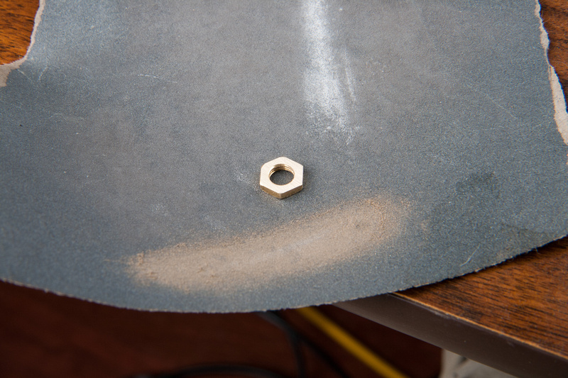
Some 220 grit sandpaper does the trick.
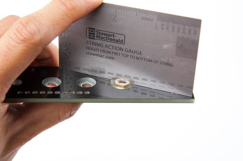
p156401396-4.jpg


p492057572-4.jpg


Fits now.

p158671637-4.jpg


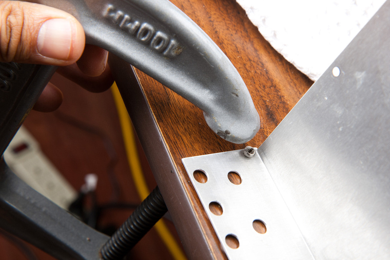
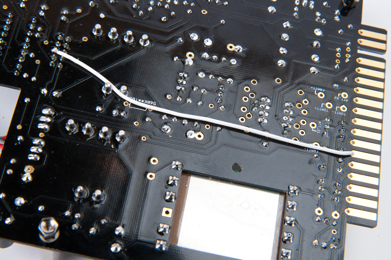
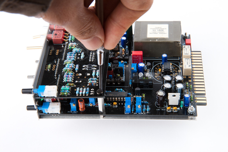
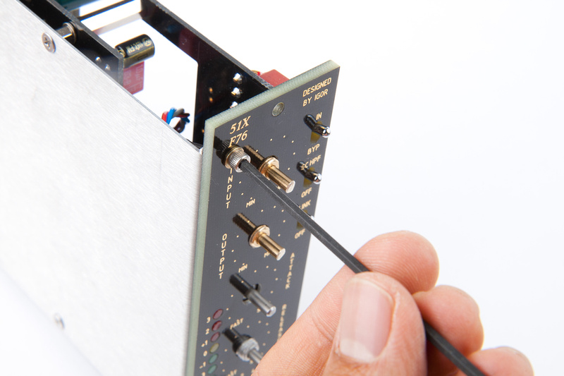
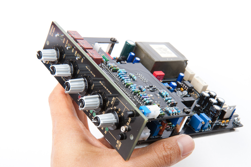
Next, I take out my jumper, attach the attack/ratio board, and assemble the whole mess again.

p152206792-4.jpg


p375371217-4.jpg


p181390021-4.jpg


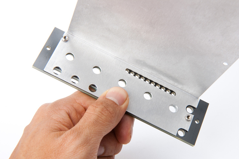
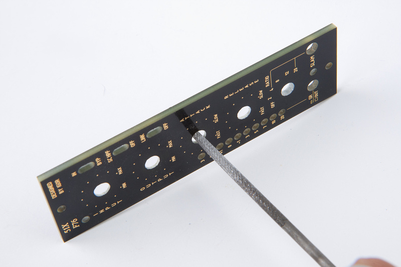
The front panel needed a bit more persuasion for everything to align, so I filed a bit on a few of the holes.
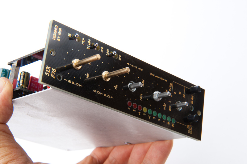
p153823392-4.jpg


Voila!

p446419737-4.jpg


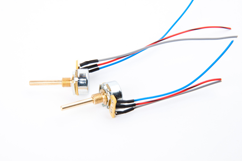
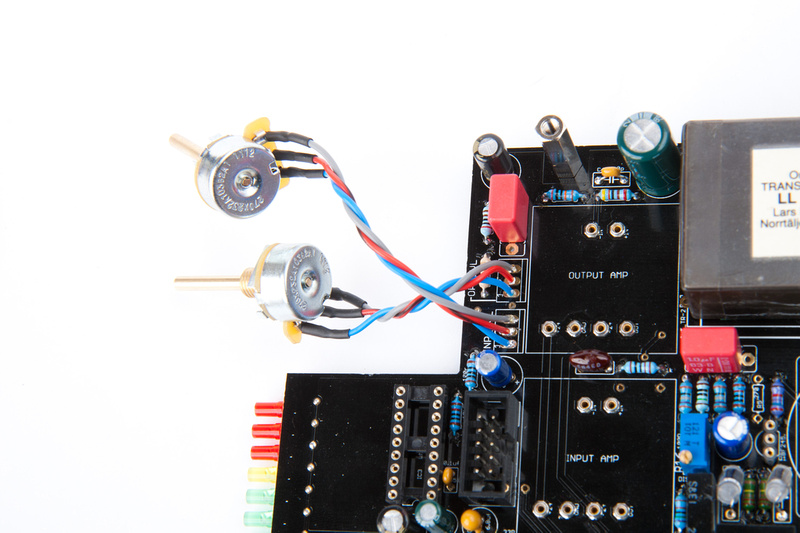
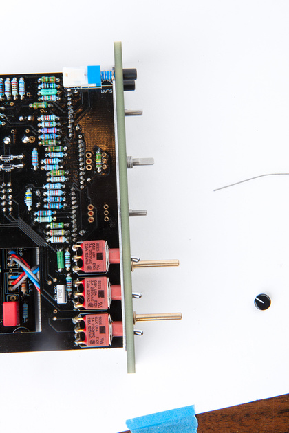
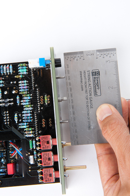
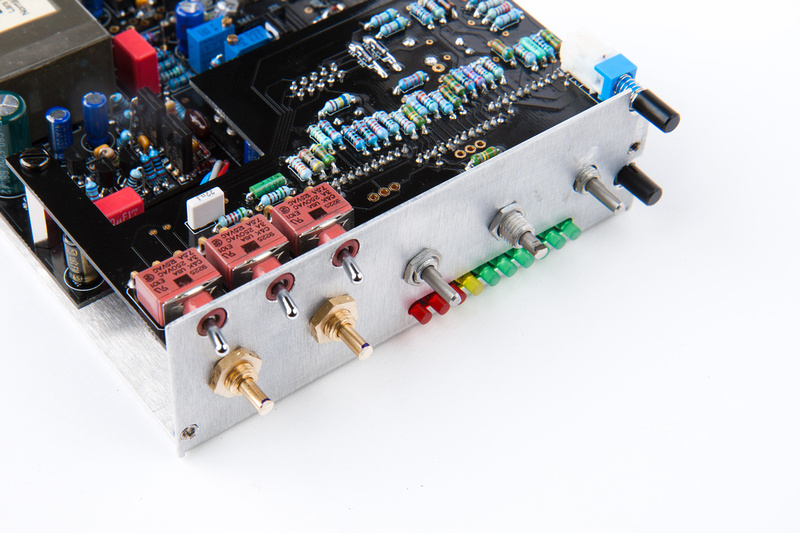
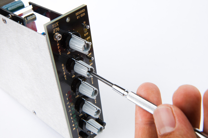
Next, I need to take care of these long pots.

p472118226-4.jpg


So, I use a straight edge and mark my cut location.

p438901041-4.jpg


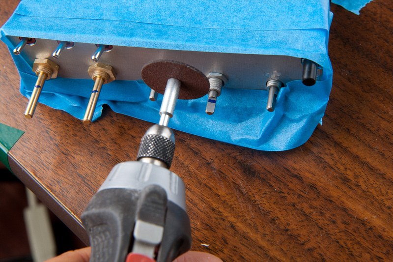
And cut with a cut-off wheel on a dremel.

p958708901-4.jpg


Voila!  Look at that precision. . . it's almost like they were cut with a laser beam.

p677594239-4.jpg


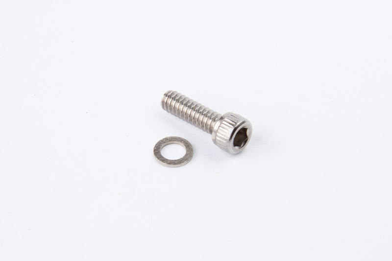
This hex screw secures the front panel to the L-bracket.  There are 2 of them.

p1021383897-4.jpg


p991559272-4.jpg


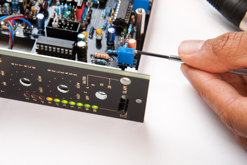
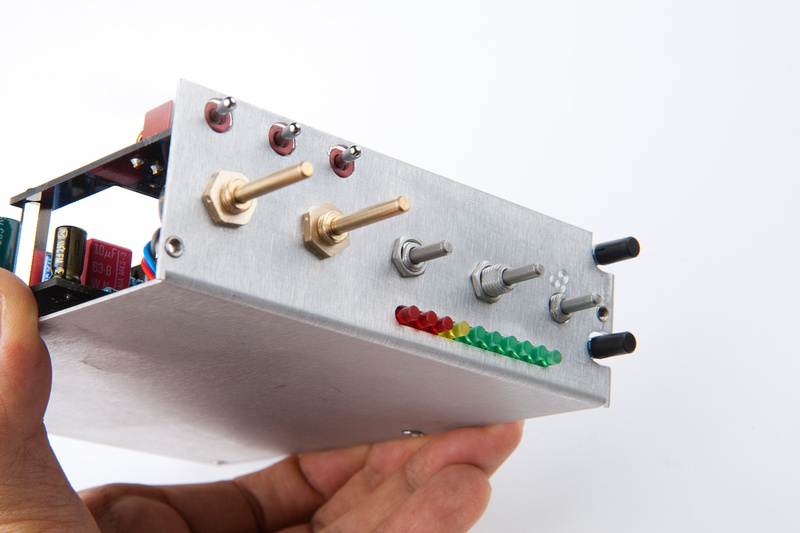
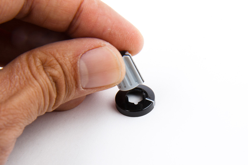
Next, I assemble knobs.

p860269521-4.jpg


And secure them to the pots and grayhill swithes.

p823546819-4.jpg


p922256589-4.jpg


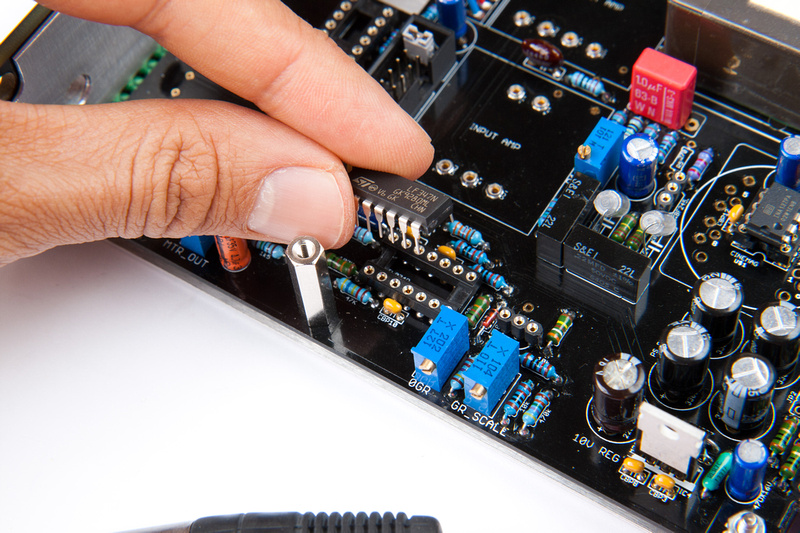
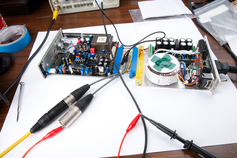
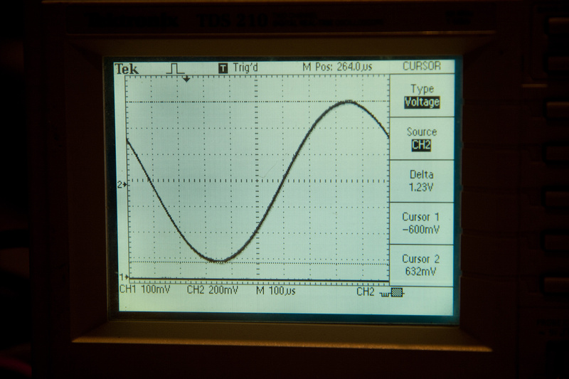
Now, I need to remove my GR and Audio fets and inject -20dB signal.  Input pot set to max, adjust output pot to 0dB or  1.23v output.

p728570821-4.jpg


p587507700-4.jpg


Then, I re-install the audio and GR FETS and adjust bias for -1dB.

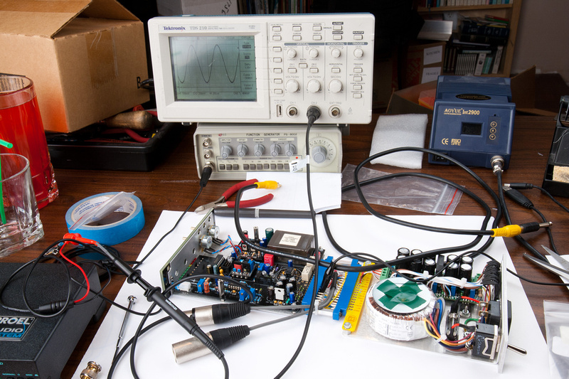
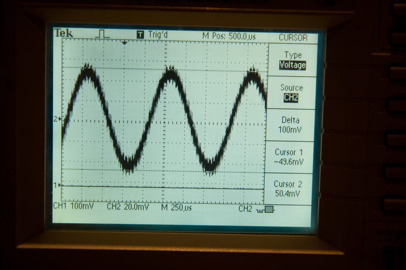
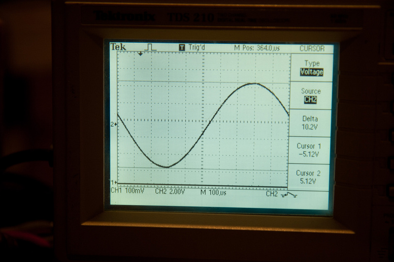
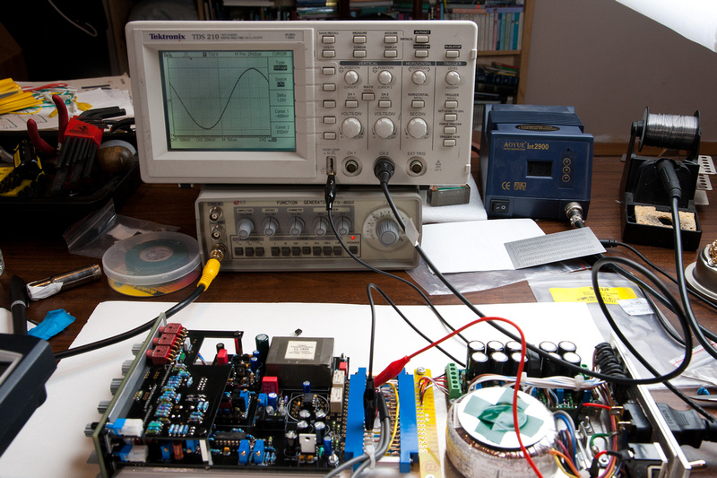
Next, I adjust the Dist trim pot. . . I read the instructions and didn't quite understand the adjustment so I just put the ouput on the scope, turned the output until I saw distortion on the sine wave, and twisted the adjustment pot.  So, it shifts the distortion more towards the top or bottom of the waveform.  I adjusted until it was even top and bottom upon distortion which would give me the greatest gain before distortion.  I twisted the output pot back and forth from clean to distortion and toyed with it until the top and the bottom of the waveform flatten out at the exact same time.  It was at a pretty close setting actually prior to starting.

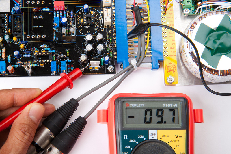
Next, I unplug input signal, put in GR mode and adjust 0GR trim pot for yellow LED to just light.

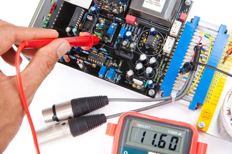
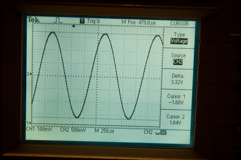
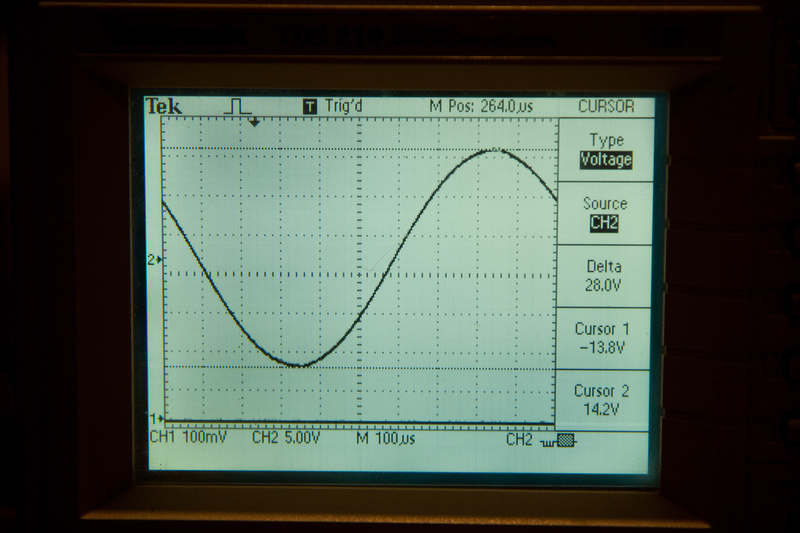
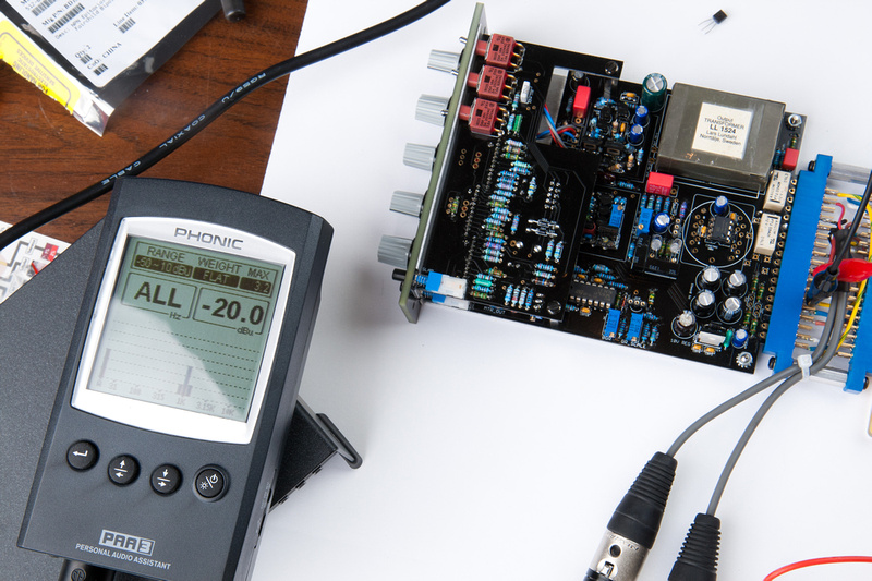
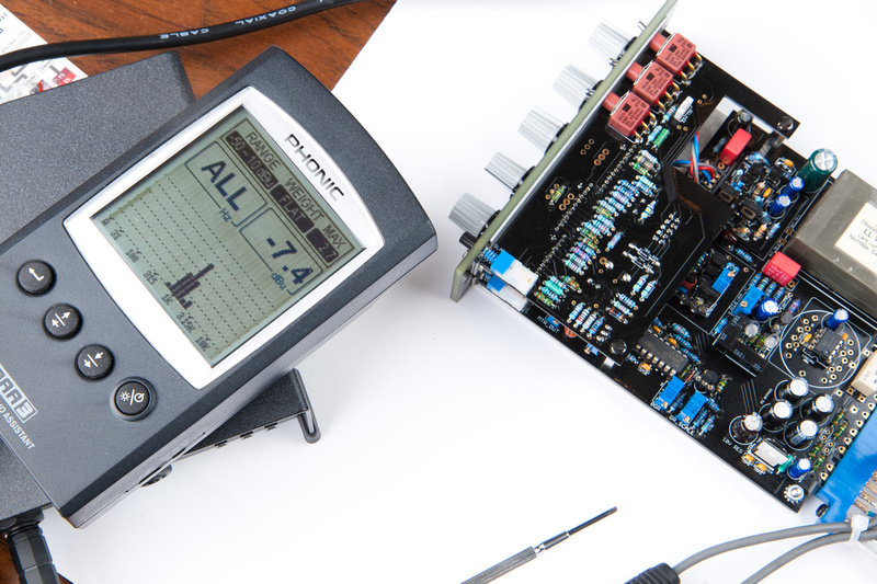
Then, I feet 0dB into the input, set ratio to 4:1 . . . and flip back and forth between OFF and 4:1 ratio.  I adjust the input pot until I find the point where the difference between 4:1 ratio and OFF position is 10dB.

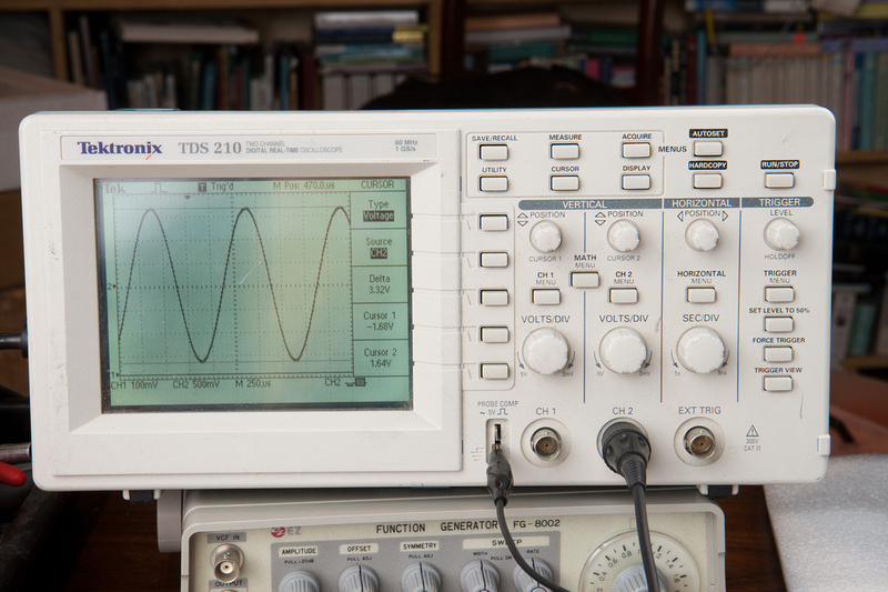
Here's my reading at 4:1 ratio.

p846522103-4.jpg


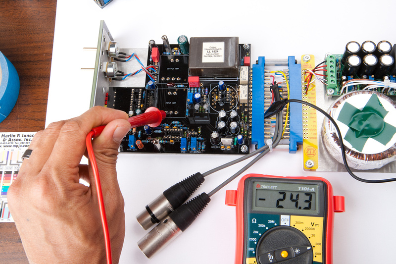
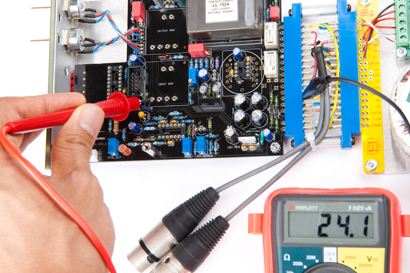
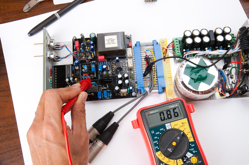
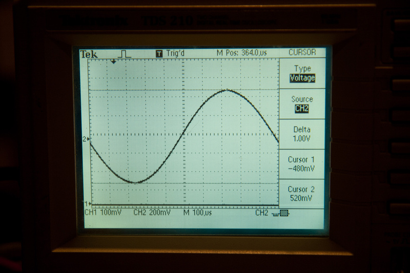
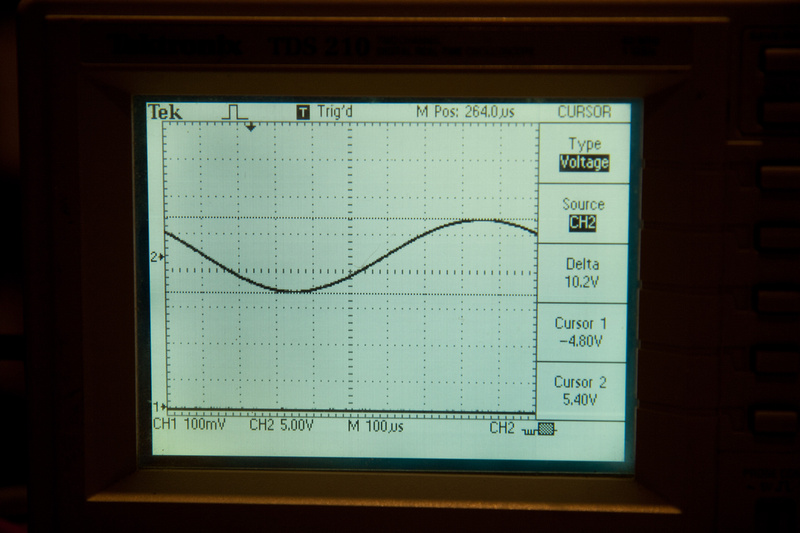
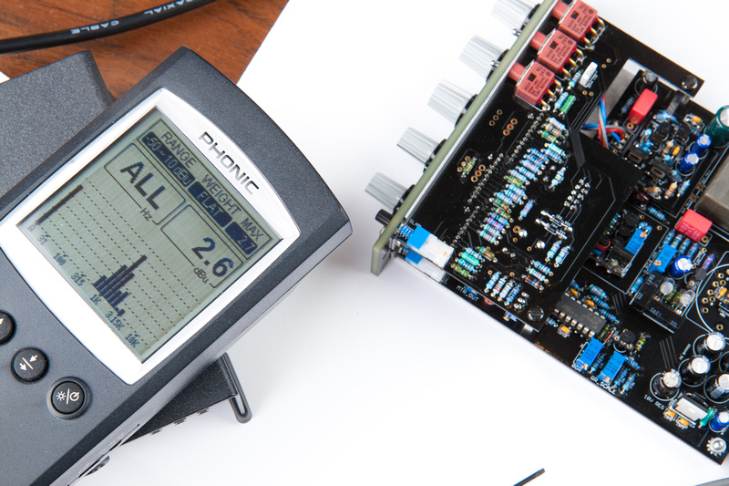
And my reading at OFF ratio.

p910124615-4.jpg


At this point, I return the ratio knob to 4:1 and adjust the GR scale trim pot until the meter reads -10

p692764152-4.jpg


At this point, the unit is calibrated and ready to run.  Humans Win!

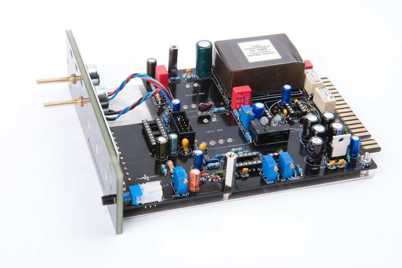
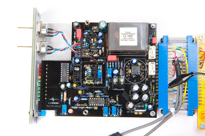
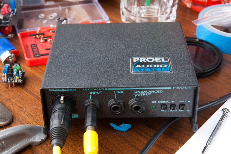
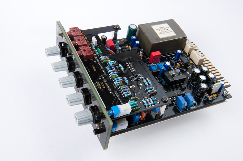
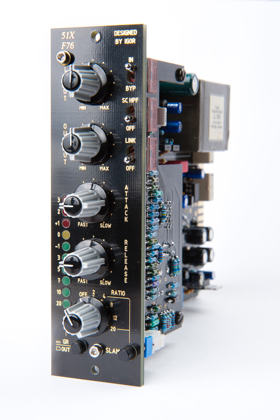
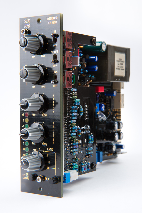
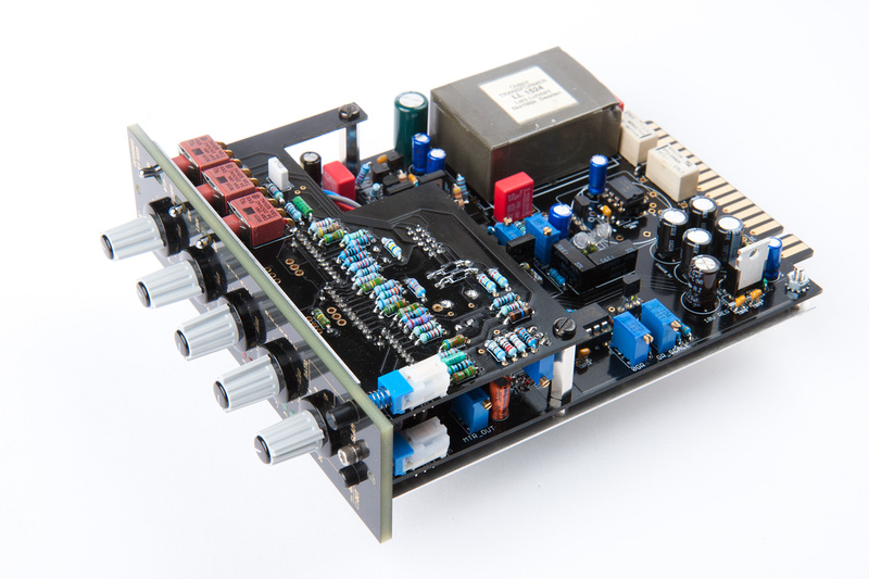
The only remaining step is to put the caps on the knobs and take pretty pictures of the finished product.

p846441576-5.jpg


p789414964-5.jpg


p817347398-4.jpg


p914200996-4.jpg


p912041504-4.jpg


p689904404-4.jpg


p707096027-4.jpg


p857716982-4.jpg


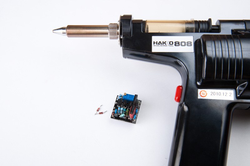
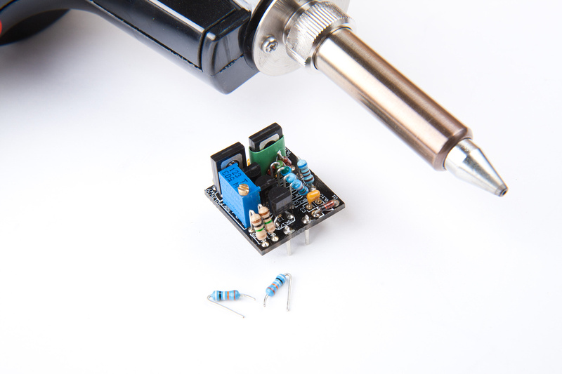
Well, there it is.  Now that I'm done taking pictures, I can try to figure out what is broken with the 1st Cascode type input amp and build my 2nd kit.  I learned a lot from this project.  It was the 1st time I used a scope.  I was trying to figure out why the math all didn't work until I figure out unity is 4dB not 0dB for this equipment.  I learned a bit about output transformers and floating ground.  And I learned hot to use my Hakko 808 desoldering tool a lot better :p

Well, I hope this gives everyone a getter look at the F76 project.  Most of the calibration steps can be done with a volt meter or plugged into a DAW.  One step (dist adjustment) is best done with scope.  I chose to use the scope for many of the calibration steps because it's a new thing for me to learn to use.

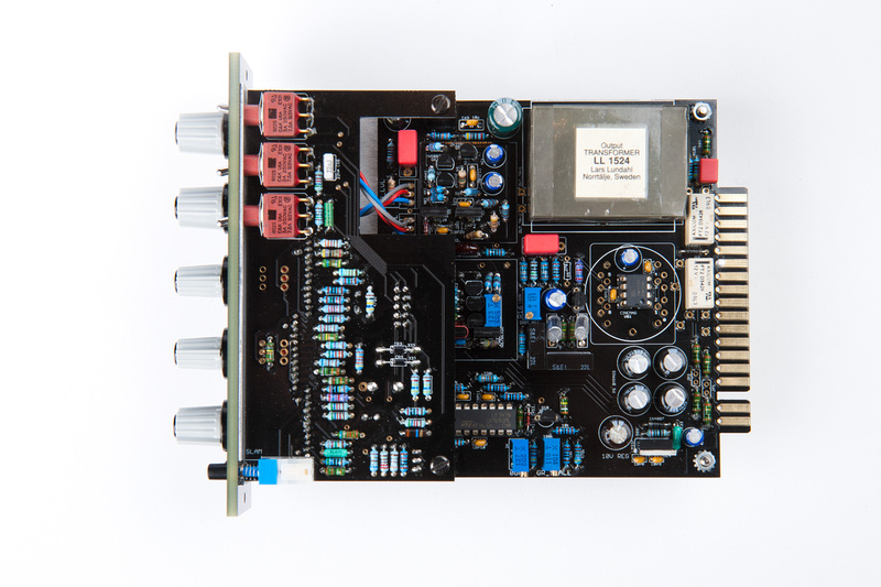
I'd say this project mechanically is not the simplest and there are a few mechanical tolerance oddities and more general futzing than some other kits, but in the end, I think the final product if carefully assembled polishes out really nicely.  The internal component arrangement is slick, and the feature set is awesome.  2:1 ratio and true relay bypass is awesome.  The metering is a treat to use.  I really like the way Igor set up the physical metering and programming to drive the meters.  Very intuitive in use.  I can't wait to get this module into the studio and hear it in a good listening environment.


Congrats,that is very impressive,and you've done this pretty well!
Now that teases me to build some on my own ;D

Cheers,have fun with the new toys,

Udo.
 
Great pictures!!!
Yesterday I mixed the first show with my new 51x-F76 on bass and leadvocals. They certainly do the 1176 thing, exactly what I wanted them to do.
Thanks a lot, Igor, for that great project!
 
Does anyone know the correct way to wire the B111048?

Currently I have primaries and secondaries in parallel, but this seems to result in low output.
 
briomusic said:
Does anyone know the correct way to wire the B111048?

Currently I have primaries and secondaries in parallel, but this seems to result in low output.

I wired in parrallel as well as Rev. F/G, using original Amps, no signal loss on my side...
On my build the low output i had on my second module, was a wong resistor on the ratio side
 
thanks zayance, I am using the ic output, which apparently noone else here does (I am tied to 511 specs for this build).
I am not quite sure what sort of level I should be seeing pre-transformer....
Was your ratio-board fault also noticeable with the ratio switch set to off?

cheers
brio

zayance said:
briomusic said:
Does anyone know the correct way to wire the B111048?

Currently I have primaries and secondaries in parallel, but this seems to result in low output.

I wired in parrallel as well as Rev. F/G, using original Amps, no signal loss on my side...
On my build the low output i had on my second module, was a wong resistor on the ratio side
 
IM nearly complete w/ 2 units.  i went to calibrate and both units seem to pass signal directly thru the units with no power.  I just plugged into my test card,  sent a sine wave and the signal passed right thru.  Almost like the input/output is shorted.  is this supposed to happen?  anyone have any idea whats going on?  the same on both units,  eveything looks ok though.

using balanced line receiver, b11148,  +-16v (500 spec)
 

Latest posts

Back
Top