MILA-1 finally done... now how do I track down that "spike"?

GroupDIY Audio Forum

Help Support GroupDIY Audio Forum:

This site may earn a commission from merchant affiliate links, including eBay, Amazon, and others.

dustbro

Well-known member
Joined
Feb 1, 2006
Messages
665
Location
New York - USA
Hey Guys,
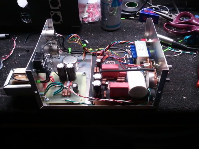
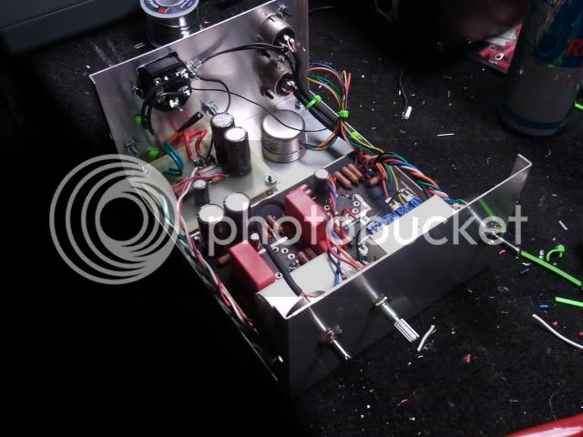
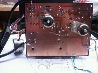
Finally finished building a MILA-1. This thing sounds amazing! Huge! I did a quick layout in PCB Artist (sorry P2P guys  :( ) and threw it into a little hammond box.

2011-04-07001218.jpg


2011-04-07001227.jpg


00000314.jpg


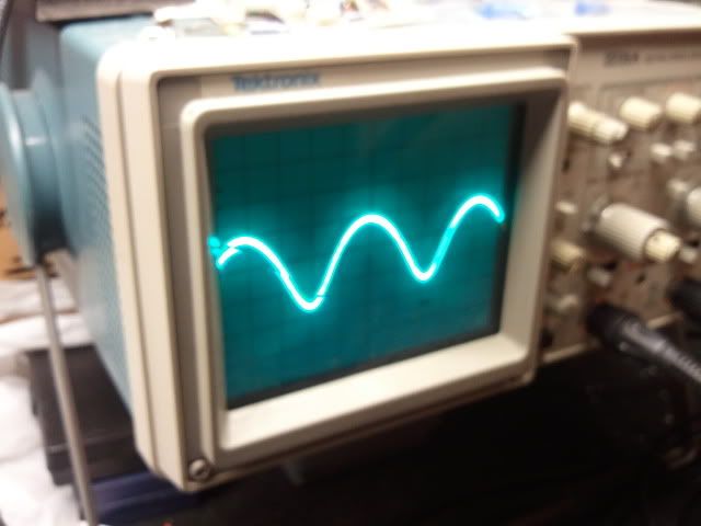
I noticed with my initial tests that I could see (but not hear) a bunch of ticks in my audio. I took it into the shop and checked it out with the scope, and this is what I saw.

2011-04-07004149.jpg


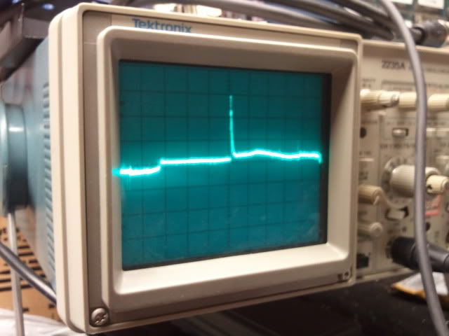
Seems to start happening right around the junction of R9/R10. At that point I can see little tiny ticks on the scope. By the time I hit C6 it's a full blown spike. Also, turning up VR1 makes them disappear.
Does anyone know what could be causing this? Power supply? bad grounding?
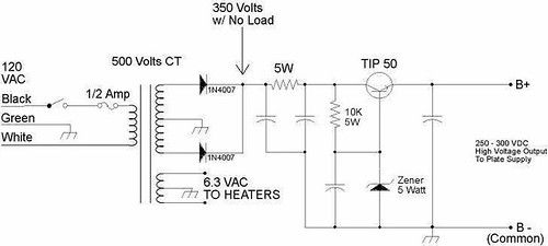
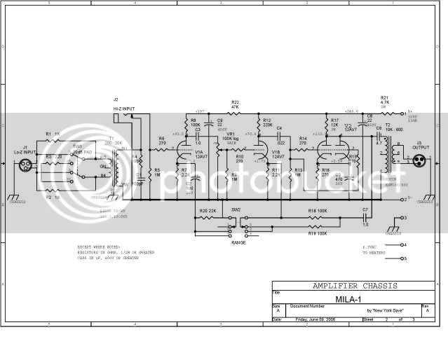
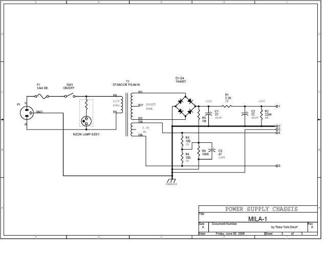
Here's the schematic I was working from

MILA1-Updated1_Page_2.jpg


MILA1-Updated1_Page_3.jpg


Thanks in advance!
Dan
 
dustbro said:
Does anyone know what could be causing this?

Your layout is highly suspect. Not so much the general layout but trace width. It is tiny! :eek: I can see B+ lines right next to a ground plane with what I suspect is smaller than 0.5mm spaces in-between. Even if you have super SMD PCB etch guy this will cause all manner of strangeness; "ohmic effects". Weird capacitive couplings and plain old high resistance "resistors" between traces. The very high voltage of B+ line will do everything in its power (pun intended) to jump traces, and you get cool little oscillators and motorboat races.

You really shouldn't have done the ground plane.
 
I notice there is no snubber capacitor across the HT secondary. Those spikes look just like diode switching spikes which such a cap is intended to suppress. Try placing a 100nF suitably rated plastic cap across the HT ac as close to the four rectifiers as you can get.

Cheers

Ian
 
Thanks for the replies! I appreciate all of the comments
I have used this format/layout for a couple other tube projects without any issues, so I'm inclined to think that the layout isnt the issue (although all of these comments are valid). Would you guys feel it was a better layout if the B+ and ground were on different layers?
After poking around I realized that I had the gain pot hooked up wrong. Did a quick rewire and now its 90% tick free  ;D
Now on to problem #2... it has a bit of a hum when the amp is cranked. At normal operating levels I really cant hear it, but my conscience wont let me move on without finding the problem.
Im using a Sowter 9610f transformer on the input, but realized that the schematic has a zobel network for the Beyer transformer, so I pulled R4/C1 and the hum got lower. I replaced all of the hookup wire going to the pad, range switch, and gain pot with shielded cable and the hum got even lower.
I may be just a little confused on the grounding scheme of this project. This has B-, and chassis.... can someone shed some light on this area? I'm assuming that B- is GND. For instance, the power supply schematic has point 3 going to chassis.. and on the circuit schematic, point 3 just says chassis (nothing is connected to it)

ruffrecords said:
I notice there is no snubber capacitor across the HT secondary. Those spikes look just like diode switching spikes which such a cap is intended to suppress. Try placing a 100nF suitably rated plastic cap across the HT ac as close to the four rectifiers as you can get.

Where would this be placed? from RD to GND on both sides of the secondary?

bobschwenkler said:
Do you see this anywhere on your B+?

B+ looks like this:
2011-04-07190608.jpg


Nothing gritty in there.

Kingston said:
I can see B+ lines right next to a ground plane with what I suspect is smaller than 0.5mm spaces in-between.The very high voltage of B+ line will do everything in its power (pun intended) to jump traces, and you get cool little oscillators and motorboat races.

Would this also add to hum, or is this directly related to motorboat races ?  :D
 
dustbro said:
Kingston said:
I can see B+ lines right next to a ground plane with what I suspect is smaller than 0.5mm spaces in-between.The very high voltage of B+ line will do everything in its power (pun intended) to jump traces, and you get cool little oscillators and motorboat races.

Would this also add to hum, or is this directly related to motorboat races ?  :D

The hum is very likely coming from somewhere else. Proximity of audio transformers to PSU transformer and other equipment/PSU's and Heater wiring if using VAC are the usual suspects. Revisit your pin1 and see if you have long wires with unbalanced audio that might need to be shielded somewhere else as well.

But then, it could also be related to the gaps that are dangerously tiny. At least capacitive coupling springs to mind. Next time, don't have a ground plane for a prototype at all. For simple tube projects a hierarchical ground bus - even if done as PCB traces - should provide better (safer and troublefree!) performance.
 
dustbro said:
B+ looks like this:
2011-04-07190608.jpg


Nothing gritty in there.

wait why didn't I see this before. It's impossible to say if that rectified and then poorly filtered sine wave is <0.1mV or what resolution, but why isn't your B+ a straight line? It's supposed to be "pure DC" or at least a very close practical equivalent of that. I seem to recall from my first tube project ever (NYD two bottle) that NYD's PSU's plans were lacking adequate filtering and I suspect it's the case here as well.  The simple CRC network of that PSU plan is just not enough for very high gains.

Think about perhaps adding an LC stage, or at least upgrading those filtering caps to much higher values.

I build my MILA-1 with a regulator plan adapted from Gyraf G9 and its noise floor is as black as a black mans cape. I never even tried the original passive CRC because I suspected it wasn't silent.

But then again, it could be that your B+ grounding has some simple routing error as well.
 
wait why didn't I see this before. It's impossible to say if that rectified and then poorly filtered sine wave is <0.1mV or what resolution, but why isn't your B+ a straight line?

I was thinking (perhaps hoping) that it was a measurement at the bridge rectifier cap. ;)

I think the G9 circuit is based on something like this:

324693062_1bcc2f4ae2.jpg


However I wonder if this circuit might have higher ripple rejection...

reg21.gif


...since it has a much lower impedance feedback path from the output of the regulator through to the 'constant voltage' section controlled by the Zener's and T2 (output error should be amplified by the GM of T2).  Plus, the output RC stage probably doesn't hurt either.  Lastly, having the output adjustable through a trim pot (rather than changing Zener diodes) might be helpful from a prototyping point of view.

 
Matador said:
I think the G9 circuit is based on something like this:

324693062_1bcc2f4ae2.jpg


However I wonder if this circuit might have higher ripple rejection...

G9 B+ is actually a floating TL789 regulator followed by an additional RC stage. It has very good performance. http://www.gyraf.dk/gy_pd/g9/g9_sch.gif

...but I've also had decent results from that zener referenced TIP50 style circuit you linked. Ripple rejection is not that great so you need decent RC or LC dropping passive filtering before the transistor, but it is a great way to ensure a stable B+ voltage compared to plain passive.
 
First question: is the hum in your signal 60Hz or 120Hz?

If it's 120Hz, try this: ground your two filter capacitors to the circuits main ground point, but don't connect them or the main grounding point to the "ground" connections on the regulator (the negative ends of the zener and its bypass cap, and the output cap). Instead, try connecting those points to each other, then connect them to the load's ground point. Connect the load's ground point to the main grounding point.

There was an article in audioXpress several years ago suggesting that this gives lower noise and explaining why (resistances in the ground connections). I've done it and it worked for me.

Peace,
Paul
 
Hey guys
thanks again for the replies! I appreciate the info
I made a new layout with ground and AC on the bottom, and B+ and audio on top. gonna pop that in over the weekend and see how it performs. It seems that the input transformer may be the cause of the hum. Touching the leads makes an audible sound like an old noisy record player. Touching the top of the transformer make a good amount of hum go away.... I wonder if I'll have better luck with a transformer that has pcb pins instead of leads.
Kingston said:
wait why didn't I see this before. It's impossible to say if that rectified and then poorly filtered sine wave is <0.1mV or what resolution, but why isn't your B+ a straight line? It's supposed to be "pure DC" or at least a very close practical equivalent of that.

I believe that measurement was taken with my scope set to AC and the division was cranked up.
I'm out of the shop for the day, so I'll probe around again when I get back.

Matador said:
I would also be helpful to know the frequency of the hum....

I'll have to measure, but it sounded like 60Hz.

 
[quote author="Kingston"] G9 B+ is actually a floating TL789 regulator followed by an additional RC stage.[/quote]

Ahh yes, I was remembering the phantom supply. ;)

I think I'll try that TL783 circuit on my next project.
 
pstamler said:
First question: is the hum in your signal 60Hz or 120Hz?

It's 60Hz

I seem to be getting quite a roll off at 100hz after the output transformer. Before the transformer, it seems to be pretty flat from 20hz to 20khz... gotta investigate that. I'm also getting a drop of about 1V on the output level when anything is plugged into it. maybe related?

 
SO... I had a star ground system that seemed to be causing the hum. The power inlet, B- from power supply, both xlr in/out pins 1, audio circuit, and input transformer shield all came together at one point on the chassis.
I now have the power inlet and B- from the power supply meet at one point on the chassis, and the rest meeting at another point on the chassis. the hum is now completely gone  ;D
I now have a tiny bit of buzz (around 2kHz) when the amp is cranked up. it seems to get better when I move the input tranformer leads around. I'm definitely going to get a transformer with PCB pins to see if that isolates the problem.
I also have a bunch of noise (pretty much a straight line from 1k up to 20k) when an unbalanced source is plugged into the input... I think the input pad is wired incorrectly, so I'm going to check to there first to see if that is the source.
 

Latest posts

Back
Top