Yet another LA-2A build log

GroupDIY Audio Forum

Help Support GroupDIY Audio Forum:

This site may earn a commission from merchant affiliate links, including eBay, Amazon, and others.

Paul Fawcett

Member
Joined
Apr 20, 2011
Messages
24
Location
Richmond, VA, USA
Hi All,

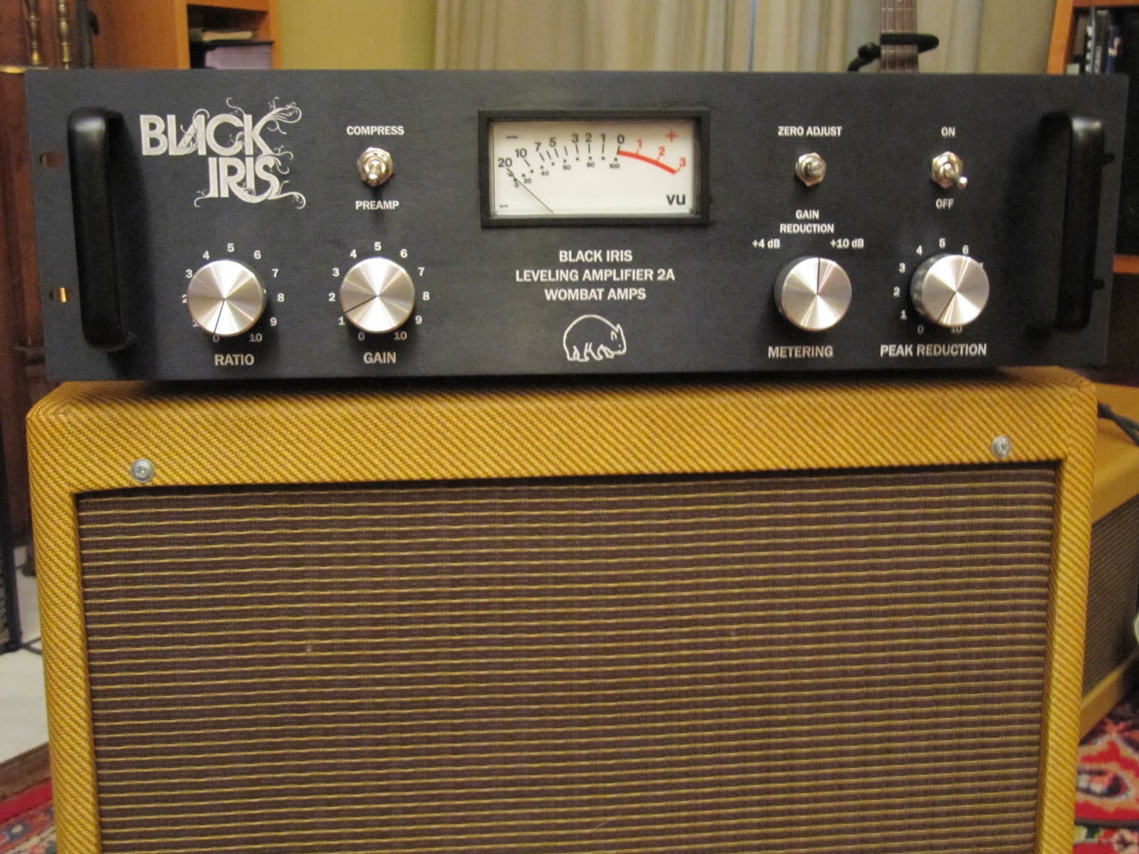
  I'm normally a tube guitar amp builder type, and usually hang out over at AX84 or the music electronics forum.. However, I had a commission recently to make for a local music collective my take on the LA-2A.  The project has turned out to be a lot of fun -- I think I'm about 3/4 of the way through now -- so I decided to blog a build log.  As there seems to be quite a lot of activity on this board regarding the LA-2A, I thought I would post the link to my build log here so that others can follow along: http://wombatamps.blogspot.com/

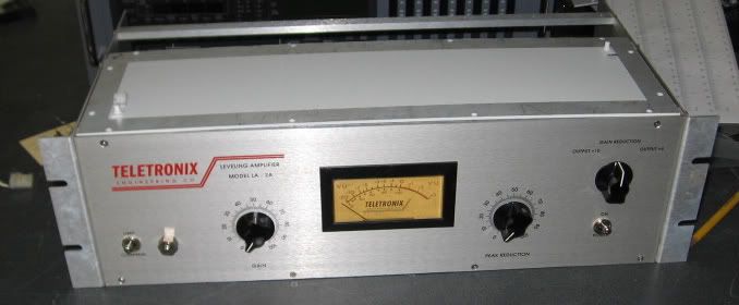
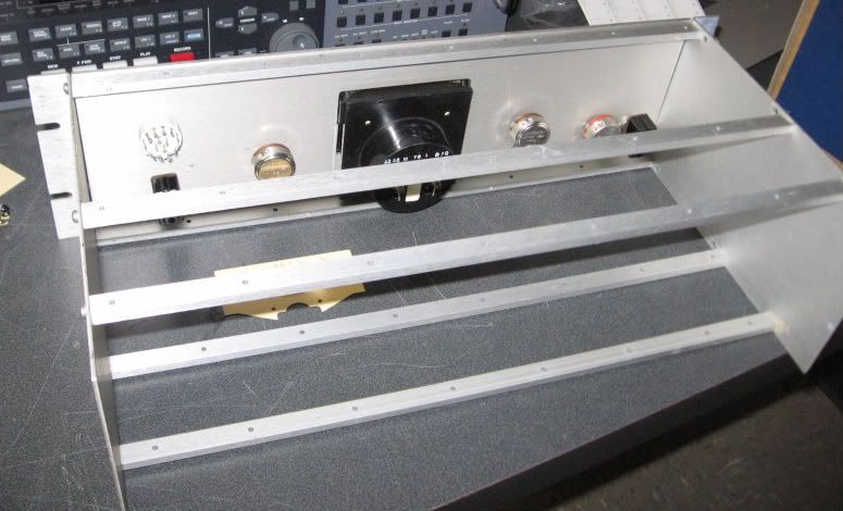
I know that it's pretty well trod territory around here, but I think there are a couple of differences between my build and the tried and true that might make the project of some interest.  For one thing, I'm using a totally rethought layout both for the circuit and for the faceplate.  Also, I've added regulated DC heaters, and made a couple of other small mods like replacing the limit/compress switch with a pot.  The iron is a Sowter input transformer, and a UTC-24 OT. Anyway, check it out and follow along with me as this heads to completion in the next week or so.

Many thanks for such a great forum, it's proven to be a valuable resource while researching the LA-2A.

Cheers,

Paul
 
Hank - we'll just have to see how the ratio pot turns out. I'm actually expecting it be, well, subtle. There's evidentally not a huge amount of difference between the limit and compress settings on the LA-2A. Basically it just replaces the 2.7k resistor and the limit/compress switch that bypasses it with a pot. I may need to experiment with pot values see what ends up giving a reasonable degree of variation across the control.
 
I was struck with the same question...

If you read my post in Pucho's thread last week where he asked if it would be an original idea to try, I posted that it won't actually work as a 'ratio' control.

It will 'tilt' the curve down a little, owing to the fact that what it's REALLY doing is moving the unit out of 100% feed-back and slightly into 'feed forward'. The resultant steepening of the curve is as a result of the 'error' in the gain reduction; it can't be counted on to actually control the ratio in any predictable way... That plus the unit is so close to being an absolute limiter in 'compress' mode, there's very little indeed that one can do.

Keitih
 
SSLtech said:
The 'compress/preamp' switch presumably just mutes the feed to the 'peak reduction' control?

Well, I hadn't actually decided yet whether to do that or to just have it lift the top of the LDRs in the T4.  Maybe you've an opinion as to the relative merits.

As for the ratio control, I'm less concerned with whether it is performing in a technical sense as a true ratio control than I am with achieving useful variation in the behaviour/sound of the unit across the rotation of the dial. I am quite aware that the effect is likely to be rather subtle. But hey, the extra knob improves the aesthetics and symmetry of the faceplate... 
 
That ratio switch is going to be way subtle. Even 5K vs. bypass, the difference is not big. Most of the time you won't notice it, sometimes it saves the day, especially on mastering or mixbus type thing. Having it under a pot is a bit overkill since the range is so limited. A single switch would have worked fine.

But what you really should have on the front panel is a control for the sidechain highpass filter. 1 meg linear pot, or perhaps rotary switch. I did a 3-way switch of bypass, 500k and 1 meg on one build. I'm was surprised it was originally a back panel "set and forget" option because it's not subtle at all.

As for that preamp/compress switch, I have a similar thing in one of my LA2A's. It bypasses the 68k series resistor of the input. A nice extra gain of about 10dB. This might make compression a bit unstable or cut bass depending on your input transformer and depending on what is driving the input, but most of the time it works fine.
 
Paul Fawcett said:
Well, I hadn't actually decided yet whether to do that or to just have it lift the top of the LDRs in the T4.  Maybe you've an opinion as to the relative merits.

I'd say absolutely DO NOT do it quite the exact way that you describe. It'll function, but you'll put yourself at a significant risk of burning out the El panel in no time at all... here's why:

The LA-2 is -fundamentally- a feed BACK topology, that means that the Gain reduction detector (the amplifier feeding the EL panel) is affected by the gain reduction.

So, if you have say about 10dB of gain reduction, both the output signal path AND the sidechain EL amplifier signal path are reduced by 10dB.

Disconnect the LDR's and the signal is no longer reduced, but the EL panel signal is now 10dB LOUDER, and so considerably brighter. This shortens the life of the panel enormously. Do the same thing by disconnecting and grounding the wiper of the 'peak reduction' potentiometer, and the same result is achieved, but using a SINGLE pole switch instead of double pole, adding no more wiring to the (noise and capacitance-sensitive due to the impedances involved) output signal path, and also makes the El panel go DARK.

By all means ALSO disconnect the LDR's if you want to remove their slight tendency to add a tiny amount of 3rd harmonic, but do not JUST do that... you'll be burning through T4 modules about as fast as you can buy them! -And for the LDR disconnects if you go that route, I'd personally be inclined to use a small relay, to keep capacitive loading and noise pickup out of the equation.

Keith
 
SSLtech said:
Paul Fawcett said:
Well, I hadn't actually decided yet whether to do that or to just have it lift the top of the LDRs in the T4.  Maybe you've an opinion as to the relative merits.

I'd say absolutely DO NOT do it quite the exact way that you describe. It'll function, but you'll put yourself at a significant risk of burning out the El panel in no time at all... here's why:

The LA-2 is -fundamentally- a feed BACK topology, that means that the Gain reduction detector (the amplifier feeding the EL panel) is affected by the gain reduction.

So, if you have say about 10dB of gain reduction, both the output signal path AND the sidechain EL amplifier signal path are reduced by 10dB.

Disconnect the LDR's and the signal is no longer reduced, but the EL panel signal is now 10dB LOUDER, and so considerably brighter. This shortens the life of the panel enormously. Do the same thing by disconnecting and grounding the wiper of the 'peak reduction' potentiometer, and the same result is achieved, but using a SINGLE pole switch instead of double pole, adding no more wiring to the (noise and capacitance-sensitive due to the impedances involved) output signal path, and also makes the El panel go DARK.

By all means ALSO disconnect the LDR's if you want to remove their slight tendency to add a tiny amount of 3rd harmonic, but do not JUST do that... you'll be burning through T4 modules about as fast as you can buy them! -And for the LDR disconnects if you go that route, I'd personally be inclined to use a small relay, to keep capacitive loading and noise pickup out of the equation.

Keith

Keith,

A very good point - I had twigged that the sidechain would be running hotter, but it hadn't occurred to me that it might actually be harmful to the EL panels to run them brighter.

I'll wire it so that the run from the peak reduction to the input is disrupted.  In your last post you mention disconnecting the wiper, and grounding the grid of the first sidechain tube.  But shouldn't it be sufficient to just break the connection to the input, and (optionally) ground the top of the peak reduction pot?  I'm thinking that the additional gain from eliminating the 68K/100K voltage divider might actually be desirable in "preamp" mode, and it would be a bit easier from the point of view of component layout.  Or do you suppose I might end up with too much gain? Note that I'm using the usual Sowter iron, not a 1:1.

Thanks,

Paul
 
You might be thinking I'm describing something a little more complicated... it's easier than that, I hope! (probably my clumsy explanation!)

Take the wire from the wiper, and switch it so that it either goes to the wiper (compress) or from ground (no compress). -no need to additionally ground the grid separately... you COULD just leave it open-circuit, but that's not good practice in high-impedance circuits of course.

Keith
 
SSLtech said:
You might be thinking I'm describing something a little more complicated... it's easier than that, I hope! (probably my clumsy explanation!)

Take the wire from the wiper, and switch it so that it either goes to the wiper (compress) or from ground (no compress). -no need to additionally ground the grid separately... you COULD just leave it open-circuit, but that's not good practice in high-impedance circuits of course.

Keith

No, your explanation was perfectly clear. The switch is clear on the other side of the chassis from the peak reduction knob however, and and doing what you suggest would require slightly rat's nest-ish wiring is all.  What I'm suggesting wouldn't directly ground the grid, but rather reference it ground. But I'm thinking the impedance at that grid node (max 25k if top and bottom of peak reduction pot are both grounded) wouldn't
be high enough to have really serious consequences for picking up noise. And I'm wondering if the increase in gain from getting rid of the 100k shunt resistance in "pre" mode might not be useful. Your opinion?
 
Paul Fawcett said:
I'm thinking that the additional gain from eliminating the 68K/100K voltage divider might actually be desirable in "preamp" mode, and it would be a bit easier from the point of view of component layout.  Or do you suppose I might end up with too much gain? Note that I'm using the usual Sowter iron, not a 1:1.

Just bypassing that 68k series resistance is enough, and also nicely lowers noise for preamp usage. That 100k (pot) against the grid with no capacitor will not do much anything so don't bother switching it out.

No there won't be too much gain. It's acting as a preamp afterall! Depending on your transformer configuration it will have 50-65dB of gain, which is good for a tube pre. Sounds great with dynamic mics.
 
Kingston said:
Paul Fawcett said:
I'm thinking that the additional gain from eliminating the 68K/100K voltage divider might actually be desirable in "preamp" mode, and it would be a bit easier from the point of view of component layout.  Or do you suppose I might end up with too much gain? Note that I'm using the usual Sowter iron, not a 1:1.

Just bypassing that 68k series resistance is enough, and also nicely lowers noise for preamp usage. That 100k (pot) against the grid with no capacitor will not do much anything so don't bother switching it out.

No there won't be too much gain. It's acting as a preamp after all! Depending on your transformer configuration it will have 50-65dB of gain, which is good for a tube pre. Sounds great with dynamic mics.

Making a few assumptions about the off resistance of the LDRs, it looks like bypassing the series resistance of 68K is good for ~7 dB increase in gain, but your suggestion of simply bypassing this keeps the gain reduction in the circuit.... could always be turned to zero, of course, but I'd prefer to have the knob position maintained.

I don't think it's fair to say the GR pot resistance has no effect... it looks to me that switching out that 100K shunt would result in about ~3dB increase in gain.

 
One thing I've observed with ALL LA-2a's which I've measured (dozens of originals and I don't know HOW many clones!!!) is that the position of the 'peak reduction' wiper varies the resistive load on the signal and causes perhaps a ~1dB change in tone output level... observed with the T4 module REMOVED, so it can't be the OPTO part of the GR circuit. -It's the resistive loading. -Of course, you probably do want the transformer secondary to see something reasonable... otherwise all sorts can happen! ;)

With the 100k pot, you could disconnect it at the top of the resistance element or the wiper (just NOT disconnect at the bottom!!!) with the same result... if you disconnected at the top, you could likely not have to ground it. If you wanted to use a 3-position switch, you could disconnect the pot in one position, and short past the 68k in another position for the extra 'boost' (DPDT center off should be wirable to do this I think) but I was thinking of just doing a single task simply... depends on whether you wanted to get more involved or not.

Either way, there's fun to be had, and at least you're trying something different! -I sort of agree about the sidechain response being a useful front panel control but I tend to LOVE the way these things look originally, so I can't really bring myself to mess up their 'original beauty' too much!

Hang on a while, and if you're interested I'll attach a pic of one I'm occasionally working on.

Keith
 
Here ya go:

IMG_5898.jpg


IMG_5899.jpg


With it looking this good so far, I can't bring myself to change the front panel...  :-\
 
SSLtech said:
One thing I've observed with ALL LA-2a's which I've measured (dozens of originals and I don't know HOW many clones!!!) is that the position of the 'peak reduction' wiper varies the resistive load on the signal and causes perhaps a ~1dB change in tone output level... observed with the T4 module REMOVED, so it can't be the OPTO part of the GR circuit. -It's the resistive loading. -Of course, you probably do want the transformer secondary to see something reasonable... otherwise all sorts can happen! ;)

I don't doubt the veracity of your experimental measurements... But theoretically, how can this be? Unless the grid is drawing grid current  -- which it definitely should not be -- the impedance of the grid itself should be extremely high -- so the position of the wiper should have no effect on the AC load on the signal.  Well, there is the miller capacitance of the paralleled tube, but even taking that into account and assuming, say, a whopping 200pF of effective capacitance on the grid, the effect on the frequency response should be inaudibly small --- about 0.2 dB of variation across the range of the pot at 20KHz, and practically nothing at frequencies where I can, you know, still hear.  And even that small degree of variation would be pretty much eliminated if the 68K series resistance is bypassed.

As for grounding the top of pot, my only thought is that it would leave the grid as a maximum of a 25K impedance node, instead of a maximum 100K impedance node. But you're right, I can't imagine it making a difference.

That's a very nice looking chassis and faceplate, it would be really hard to distinguish from the real thing!  Incidentally, do you have a part number/supplier you would be willing to share for that rotary switch?  I ended up using one of those miniature 6 Pos Greyhill jobs.. but the lugs are so darn tiny and fragile, I found it a real nuisance to work with. In fact, I managed to clumsily destroy the first one I tried.

The one you have looks friendlier, to say the least.

 
I honestly can't say how or why... Perhaps cable capaitance (I'm not thinking that's likely) but I've never looked into it...

However, with the T4 completely removed from an LA-2a, I can turn up the peak reduction with a 1K tone, and the output level sags about 1dB.

The first time I noticed this, I was looking at a unit which had a 100% dead tube in the sidechain amplifier. -I initially ruled that out, because I was seeing the level reduce slightly at the top end of the pot range. -Eventually I broke out the scope and found the problem, but I was intrigued by having been misled. The place I was at had FOUR original LA-2a's (pictured below) so I tried the same test with all of them, with the T4's removed.

Cali-all-4.jpg


-They ALL did it.

Don't get me wrong, it surprised the hell outa me!

There's a couple of UA reissue LA-2a's here... I can try it once more and maybe even video it if you like... my camera here does little 10-second mpeg thingies which could be uploaded to Youchoob.

As to WHY it happens, I've never gone so far as to chase it down.

The switch is a 4-pole 3-position LORLIN, but with solder loops/eyes instead of PC pins. They're available at Mouser I'm pretty sure. -The pots on that one are original Clarostat J-types, so the law will be correct, and the rotation stops also match the front panel labeling. -No hing on that front panel, but I've built one with a hinge before...

pair.jpg


Also, no thumb-knobs, and no screw to hold the meter illumination bulb bracket in the North-East corner of the meter...

Keef
 
Hi Keith & Kingston,

I had a chance to virtually complete the wiring today, just a couple of things to tidy up and I'll be ready to move on to initial measurement and testing.

After all was said and done, I wired up the preamp/compress switch with a DPDT, with one half bypassing the 68K per Kingston, and the other half grounding or connecting the GR pot wiper per Keith. We'll see how it suits. In the meantime, here's a snap of the finished unit:

Finished_front.JPG


There are more on the blog http://wombatamps.blogspot.com/, and I'll be sure to post up plenty of gutshots and a recap when everything is done to my satisfaction.

Thanks for all your help!

Cheers,

Paul
 

Latest posts

Back
Top