Gate charge spec for MOSFETs....I don't get it.

GroupDIY Audio Forum

Help Support GroupDIY Audio Forum:

This site may earn a commission from merchant affiliate links, including eBay, Amazon, and others.

shaddai

Active member
Joined
Dec 10, 2005
Messages
35
Location
North Idaho
So, I've been monkeying around with some 8 bit PIC microcontroller stuff & having a blast making LED's blink in all sorts of wonderful patterns  ;D I think I've found a new hobby!!

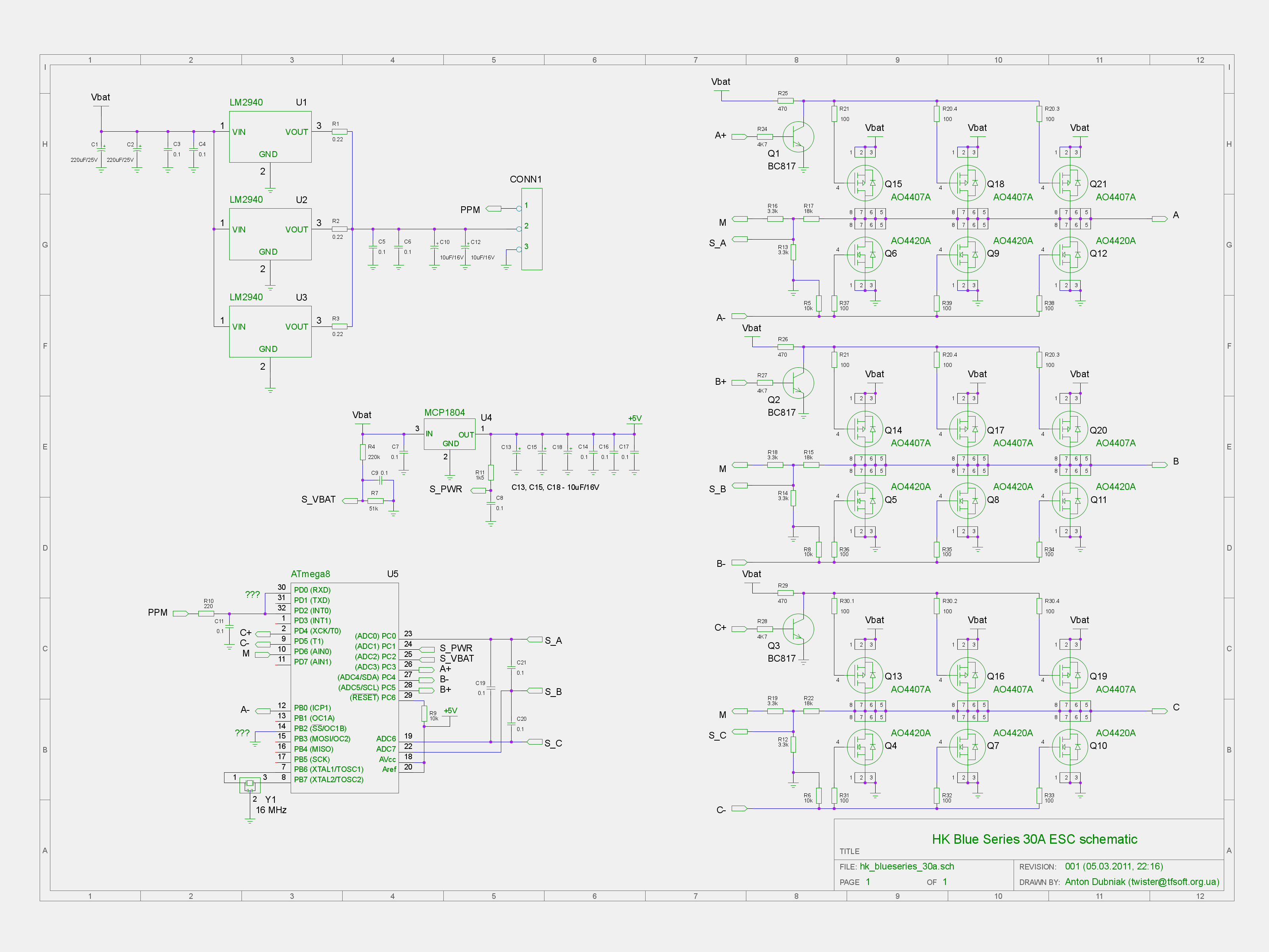
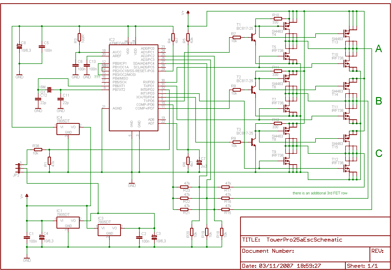
Figured I'd step it up a notch & drive a brushless 3 phase dc motor now...which leads me to having to pick mosfets to actually do the switching with the pins of the microcontroller driving the gate of the mosfet. There's where I'm struggling. I'm having a case of thick knucklehead when it comes to understanding the whole Qg specification.

I've got 5v @ 20ma to feed to a gate on a Mosfet, which will in turn switch a max of 10v @ 20A (most likely much less), but don't quite understand how to get from the available max power from the PIC & turn it into a Qg spec. Can someone wiser than I 'splain it?

Thanks in advance...

todd
 
Mosfets are switched on/off by the gate voltage, and don't require any steady state input current to stay on or off, so the PIC can drive the gate of the right mosfet directly as long as 0-5V or 0-3.3V is enough voltage to switch the mosfet, fully on/off.

One possible issue you might have is gate capacitance. If it's a high power mosfet, the gate structure will be larger and have some capacitance, so it will take a certain switching time for the PIC to charge or discharge whatever mosfet gate capacitance there is. For modest frequency switching this is not an issue, for higher switch speeds it could be.

So question is how fast do you need to switch the mosfets? and how much gate capacitance does the mosfet you want to use have?.

JR

 
I just a discussion about the gate charge in a book....it's still a little fuzzy, but I think it'll soak in :)

Anyway, 10k revs/minute (average, possibly 20k) = 166 revs/second = each phase switched around 55 hz'ish. It'll have to start the motor from still, so, the correct answer is: "a complete short" clear up to "slower than dirt". The PIC will have a startup loop it'll perform until it can detect back EMF & switch over to timing from that instead. I really don't think a delay due to capacitance is much of an issue..

And I haven't picked any mosfets yet. Trying to decipher the whole Qg specification sorta pushed me off the trail... Seems the main thing I'm up against is finding one that can use 5v at the gate and still switch 10v@20A. Am I missing anything else?

todd
 
try a search for "brushless esc schematic" (ESC is electronic speed controller, as used by rc-people)

Like:
hk_blueseries_30a.png


or:
a1555259-161-TowerPro25aEscSchematic.png


Jakob E.
 
One consideration is starts up, so you don't have MOSFETs fighting each other... The PIC generally starts up with all ports set as high Z inputs. If direct driving mosfet gates, these could start up in some indeterminate state. The schematics show using transistor pre drivers, which will be off, when the PIC starts up high Z.  You may want to use similar transistor drivers or pull-up/down resistors on the gates to insure a known start up state.

JR
 
did you try "mosfet gate charge"  using google?

There is a lot of information on the web and books for driving mosfets.
 
The energy storage capacity of a MOSFET gate during switching can't be estimated from the capacitance alone. The MOSFET Vgs stays around Vth until the gate is charged, while the device is turning on. Thus the gate charge, not the capacitance, determines the switching time. One must fully grok this in order to correctly design the switch driver circuit and conduction timing.
 
> turn it into a Qg spec

The MOSFET gate is a capacitor. You must pump 234 zillion electrons into or out-of it to make the MOSFET switch.

You can use high current, 234 zillion electrons per pico-second, and switch in a picosecond, or low current 234 zillion electrons per second and switch in about a second.

> determines the switching time

Just so.

Without doing the math which comes long-long after Ohm's Law, you can simply observe that >10KHz switches may need added gate-driver stages and <1KHz switches can be driven with very humble stuff.

> drive a brushless 3 phase dc motor

This is distinctly slow stuff. You do NOT need to compute gate charge. Be sure that +5V will allow MORE than enough drain-source current to sock your motor winding. Put a few hundred ohms in series with the gate, right AT the gate, to discourage the MOSFET from oscillationg against winding and other strays.
 

Latest posts

Back
Top