rmaier
Well-known member
Yes (at least, that's what I used for both low mid and high mid boost/cut in my build). I had a bit more time to play with the EQ lately. God, it sounds really good!
Ralph
Ralph


wave said:The mid boost/cut pot is 47K Log, correct?
Dave
Rotation                Boost                Cut
50%                     7.5dB                1.2dB
100% 15.6dB 14dBrmaier said:No wonder my mid cuts were so SUBTLE ;D ;D ;D ;D ;D
rmaier said:Thanks, Ian, but I think I'll probably make up a new set of linear switches and see how they compare. 3rd time lucky?
wave said:Gentlemen,
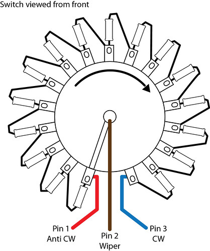
I have created a diagram for my stepped switches (I need these visual aids) and I'm wondering if you can give it a look and make sure that I'm going to do this right.
The switch is viewed from the front (shaft) side and I have labeled the connections as Pin 1 Anti CW...etc.
So if looking at my diagram, if I were using this switch as the Hi Boost Lin pot (switch) then Pin1 would be connected to T1 of the High PCB.
Pin 2 would be connected to T2 of the High PCB. Pin 3 would be connected to Pin3 of the Hi Cut switch, correct?
Conversely, if this were the Lo Boost Log pot (switch), Pin 1 would be connected to T1 of the Lo PCB while Pin 2 would be jumpered to Pin 3 and Pin 3 would be connected to T2 of the Lo PCB as well as Pin 1 of the Hi Cut pot (switch).
")
irfrench said:Ian,
Ha ha, Thanks for getting back. I'll update the schematic & layout to include those changes. If you don't mind airing laundry in public - what do those changes provide/produce/prevent?
Thanks,
Ian


Enter your email address to join: