Poor Man's Pultec EQP1-A Build Support Thread

GroupDIY Audio Forum

Help Support GroupDIY Audio Forum:

This site may earn a commission from merchant affiliate links, including eBay, Amazon, and others.
Humner said:
Do you think you could get away with using a SPDT switch instead? in other words, can you tie and output of the passive EQ and the output of the Pad together going to the makeup gain, and then just switch the input? Or the other way around?

You cannot tie together the output of the EQ to the output of the pad because the pad would load the output of the EQ and seriously distort its response. However, if you want to get away with a SPDT switch you could tie the inputs of the EQ and the pad together and switch the outputs. This will work but it is not ideal. Both the pad and the EQ are designed to provide a 10K load to the input transformer. If you connect the two inputs together the load becomes 5K. Provided whatever you drive the transformer with has a low output impedance then this will made little if any difference. If it does not then you could lose some bass response and, even with the EQ bypassed, its changing input impedance with frequency could alter the frequency response. I have never tried it but it will not do any harm so I suggest you give it a try.

Cheers

Ian
 
thanks ian. Very helpful.

i ended up positioning the IN/OUT switch on my panel in a bit of a tight spot and found I could only fit a SPDT toggle in.

I'll do some testing when peters inductors arrive. Worst case I use relay's.
 
Hi Ian,

Another question.

I'm using this gain stage - https://dl.dropboxusercontent.com/u/91809016/MY_Circuit.pdf

What would you recommend for values for the input trim pot as I saw that your eq system guide shows 470k pot - http://www.ianbell.ukfsn.org/EzTubeMixer/docs/PMEQP1A/EQSystem.png

Should I replace the 10k pot with 470k pot - do I require any further input resistors?

Thanks for your time. Rob
 
Hi Rob,

The amp schematic you posted consists of a Darlington pair of input transistors as a gain stage followed by a regular totem pole output stage. As there is only one inversion (due to the Darlington) the NFB has to be applied at the amp input (dc NFB via the 1.5Meg and ac  NFB via the 220K). The gain is set by the ratio of the 200K divided by the value of the input  trim pot. Unfortunately, the input impedance is also determined by the value of the trim pot so it will never be more than 10K (the NFB makes the bas of the first transistor a virtual earth). 10K is far to low a load for the poor man's EQP1A. I am not 100% sure we can cajole this into working properly with the EQP1A.

We need about 20dB of gain make up. If we removed the 220K ac feedback resistor and replaced the trim pot with a 220K we might have a solution. The 1.5Meg now provides both the dc and ac feedback. The 47uF output cap is no no longer in the feedback path but I do not think this is important. If you feed the output into a 10K load, the response will be 3dB down at 0.33Hz.  The trim pot will end up at around 150K for 20dB of gain make up. This is a little on the low side but not enough to make the EQ unworkable.

Is this your own design?

Cheers

Ian
 
Hi ian,

Thanks for that explanation, I now have a much better understanding on how this particular gainstage is working and will have a play around with it.

Its not my design, you will find further details here -  http://groupdiy.com/index.php?topic=59222.0 - I've been playing around with it as an alternative to a 2520 gain amp I was planning on using so no big fuss if I run into some roadblocks.
 
OK, understood. It did not want to criticize the design until I knew whose it was. That circuit, as it stands, is quite primitive as regards the way it biases the first stage. It is very hard to determine at what dc voltage the output will sit and it depends a lot on the gains of the transistors used. It was a common bias method in very early designs. If you look here:

http://s26.photobucket.com/user/rascalseven/media/PEQ-2Acircuit.jpg.html

You will see the improved version that removes the dependence on transistor gain but it does require an extra transistor. It also disconnects the gain control form the input circuit so the input impedance is not changed as you change the gain. The input impedance is also a little higher. However, this circuit is still not ideal. First it uses a pot divider (1Meg and 47K) straight across the power supply to bias the first transistor. This gives it a nice 'stiff' bias voltage but any noise on the supply is injected directly into the base of the first transistor - not a good idea. I have not been able to find a later version that addresses these problems.

I guess the bottom line is that discrete transistor design is just as hard as tube design and there are plenty of designs out there that would better suit your purposes.

Cheers

Ian
 
Hi Ian,

Had a play around with this today and came up with a solution.

I have built an extra board using vero - it handles the IN/OUT relay's, the pad and pad trim, and also a jfet impedance buffer(not that there was anything wrong with your solution).  So before it gets to the gain stage the Poormans EQ gets the high impedance it wants/needs.  The circuit was simple enough, 1 transistor, a few caps + a few resistors. Best part is that I learned a lot today!

I tested with EQ without inductors installed and the low boost + cut works well and as expected - it was only tested by ear but a promising result nonetheless.

All and all a good day. Big thanks for your knowledge and wisdom and quick response - its always appreciated.
 
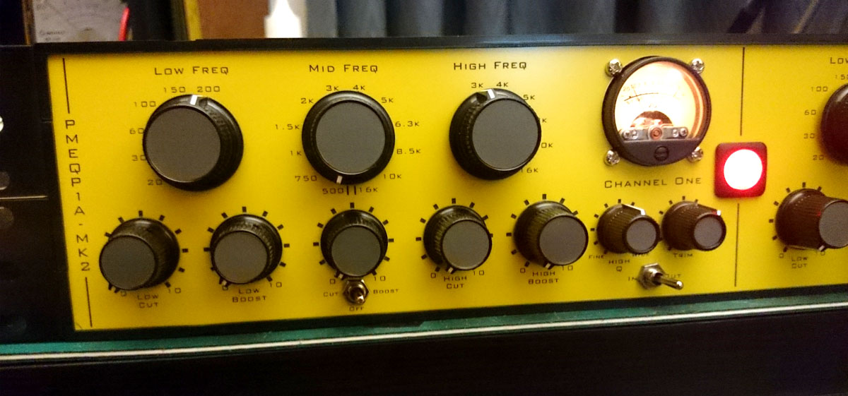
While I wait for peters inductors I thought some pictures of the front panel + knobs is in order.

I took these while doing testing of gainstage  + in/out. Its working very well. I can only test the low boost/cut and high cut, but these are working as expected so far, once the inductors arrive I can do the final test, but so far its looking very promising.

1.jpg


2.jpg
 
This is really great design.

About my gain stage,i understand what's wrong but it's fine with my pultec.I can't see any problem.But if we have to add impedance matching circuit(hi-z to low-z),we can use interstage transformer,too.Am i right?If we can use transformer,can you recommend any transformer or ratio?10K:600 or what?
 
ForthMonkey said:
This is really great design.

About my gain stage,i understand what's wrong but it's fine with my pultec.I can't see any problem.But if we have to add impedance matching circuit(hi-z to low-z),we can use interstage transformer,too.Am i right?If we can use transformer,can you recommend any transformer or ratio?10K:600 or what?

A transformer might work if you used one of those intended for DI applications. However, the step down ratio means you need even more gain make up and this would probably  lead to noise problems so I would not recommend it. Way back in the early days of the design there was a lot of discussion of this topic and some interesting solutions were presented. I suggest you search through the original threads for them.

Cheers

Ian
 
Hey fellow builders!

Anyone know a source for a power transformer for this project? I've got a dual channel build with Ian's EQP1A, PMMID and PMTGMU (+ HT Supply PCB) - been trying to hunt down a trafo, no luck by far :(

Any ideas very welcome!

Cheers,
Jarkko
 
troubleous said:
Hey fellow builders!

Anyone know a source for a power transformer for this project? I've got a dual channel build with Ian's EQP1A, PMMID and PMTGMU (+ HT Supply PCB) - been trying to hunt down a trafo, no luck by far :(

Any ideas very welcome!

Cheers,
Jarkko

The power requirements of the two amplifiers are very modest and as far as I know there is not a transformer that exactly fits the bill. As a result, most people end up using a transformer that is a little bit of an overkill but nonetheless works well. I have heard that many people use an Antek  AS-05T240 - 50VA 240V transformer:

http://www.antekinc.com/as-05t240-50va-240v-transformer/

Don-Audio also makes one that you can use that was designed for the Mila project:

https://www.don-audio.com/Toroidal-Transformer-Mila-sec-250vct-63vct-48V

Right now, Don-Audio is designing a custom mains toroid for me for the Classic Solo project which is basically a pair of PMTGMU circuits and a power supply on one board. THis transformer should therefore also be ideal for powering a couple of PMTGMU boards. The prototype board is due at the end of September.

Cheers

Ian
 
Another question for the wise:

What's would be the wisest way to hook up a pilot light - preferably led - when having dual channel build (Antec feeding two PMTGMU's from 6.3V)?

Cheers,
Jarkko
 
troubleous said:
Another question for the wise:

What's would be the wisest way to hook up a pilot light - preferably led - when having dual channel build (Antec feeding two PMTGMU's from 6.3V)?

Cheers,
Jarkko

I would suggest you power it from the 6.3AC winding via a suitable current limiting resistor. As the supply is AC you should add a diode across the LED to limit the reverse voltage across the LED - a 1N41418 should do it. LEDs typically draw 10 mA so  series resistor in the region of 620 ohms should be about right.

Cheers

Ian
 
Hi,

Bought most of the parts for my build now and started preparing everything (building a stereo version with poor mans make up gain). I just wanted to make sure this power transformer would work ok? Specs show 2x6v secondaries 50va. I'm in the UK.

http://www.ebay.co.uk/itm/201257651358

Thanks
Paul
 
unklepablo said:
Hi,

Bought most of the parts for my build now and started preparing everything (building a stereo version with poor mans make up gain). I just wanted to make sure this power transformer would work ok? Specs show 2x6v secondaries 50va. I'm in the UK.

http://www.ebay.co.uk/itm/201257651358

Thanks
Paul

That will do for the heaters but it is rather overkill. Even if you use 6CG7 tubes, the total heater current is only 1.2A which  is a power requirement of just just over 7.5 watts so a 10VA or 15VA  transformer would be more than enough. Don't forget you will also need a transformer for the HT voltage.

Cheers

ian
 
ruffrecords said:
unklepablo said:
Hi,

Bought most of the parts for my build now and started preparing everything (building a stereo version with poor mans make up gain). I just wanted to make sure this power transformer would work ok? Specs show 2x6v secondaries 50va. I'm in the UK.

http://www.ebay.co.uk/itm/201257651358

Thanks
Paul

That will do for the heaters but it is rather overkill. Even if you use 6CG7 tubes, the total heater current is only 1.2A which  is a power requirement of just just over 7.5 watts so a 10VA or 15VA  transformer would be more than enough. Don't forget you will also need a transformer for the HT voltage.

Cheers

ian

Thanks Ian I was hoping to wire my pair similar to Daveseqp-1ahookup.pdf on your dropbox documents. I went for the stereo pair of mk2 boards with x2 poor mans make up and psu board. I thought I only needed the 1 transformer to power it all. 

Stuffing the boards is giving me time to figure this part out so not rushing into it
 
Back
Top