HT Regulated Power Supply

GroupDIY Audio Forum

Help Support GroupDIY Audio Forum:

This site may earn a commission from merchant affiliate links, including eBay, Amazon, and others.

82Hz

Member
Joined
Dec 18, 2008
Messages
15
Location
Italy
Hi everybody, i am trying to build a regulated power supply for a guitar tube preamp.

I found that schematic:

reg2.gif


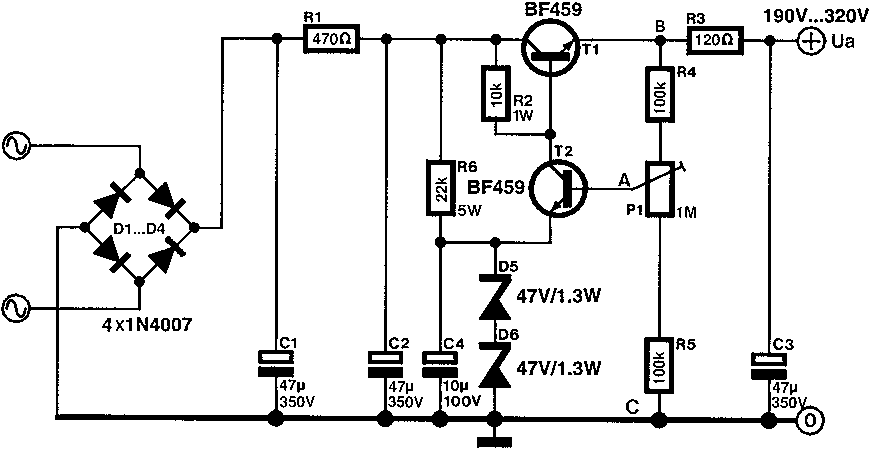
from www.bonavolta.ch.

I need a 320V DC, i use BF471 transistor each with a dedicated heat sink and it work fine for regulate voltage but i have bad ripple output and lot of noise.
I use a 280 VAC as input with a 4A bridge rectifier. I try to increase C1, C2 capacity with no great result.
I can post some scope photos of output noise.
What is wrong with this schematic?
 
Shunt a 1uF film cap from the base of T2 to the emitter of T1 (point A and B). Make sure it is not electrolytic. Other tweaks could be increasing the value of R2 to 22K and changing T2 to MJE340.
 
+1 for the 1u cap, but do not forget to add a diode (another 1N4007) between T2 base and emitter (point A and T2 emitter), cathode at T2 base, to protect T2 from reverse B-E voltage.
 
82Hz said:
Hi everybody, i am trying to build a regulated power supply for a guitar tube preamp.
First, I think you don't need a regulated PS for a guitar preamp! OK, I understand that you want to experiment.
I need a 320V DC, i use BF471 transistor each with a dedicated heat sink and it work fine for regulate voltage but i have bad ripple output and lot of noise.
I use a 280 VAC as input with a 4A bridge rectifier. I try to increase C1, C2 capacity with no great result.
I can post some scope photos of output noise.
What is wrong with this schematic?
There is nothing really wrong with this schematic. It should work. It's pretty standard.
You need to check the reference voltage at junction of T2/D5/R6/C4. If the reference is not clean, the output voltage cannot be clean.
Can you post the 'scope pix at this point and at the output?
What's the DC voltage at C1?
How have you done the prototype? PCB, point-to-point, breadboard?
As you know, grounding is paramount in a power supply, maybe you have a problem there...
 
but i have bad ripple output and lot of noise.

It would be useful to know exactly what 'bad ripple output' and 'a lot of noise' are in numbers.

I would suspect grounding as well.  When I tested this circuit, it was imperative to have the grounds such that the first cap had a really solid connection (e.g. low resistance) to the bridge rectifier junction.
 
Matador said:
When I tested this circuit, it was imperative to have the grounds such that the first cap had a really solid connection (e.g. low resistance) to the bridge rectifier junction.

Isn't it always? Primary cause of ripple right there. Just like when the first cap dries out, no amount of subsequent filtering will really get rid of it.


Latest posts

Back
Top