Old Philips-NEFA 2891 A Tubemicpre - Troubleshooting

GroupDIY Audio Forum

Help Support GroupDIY Audio Forum:

This site may earn a commission from merchant affiliate links, including eBay, Amazon, and others.

Baltazar

Well-known member
Joined
Oct 9, 2006
Messages
49
Location
Stockholm, Sweden
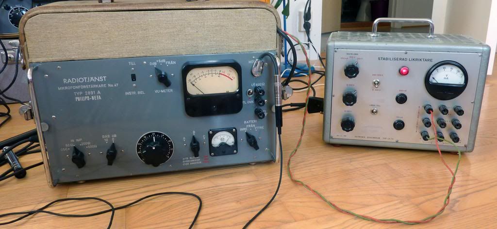
I found this on the Swedish "ebay" and couldn't resist, never seen anything like it and the condition is very good! :)
Built in to a suitcase and with an external power supply.
From what i know it's build by Philips-NEFA around 1959 for the Swedish radio.
The guy i bought it from had a tech to look over the power supply, and that part looks safe, all the bigger tubes are replaced, and it has been functional.
However no audio is passing thru the unit anymore.
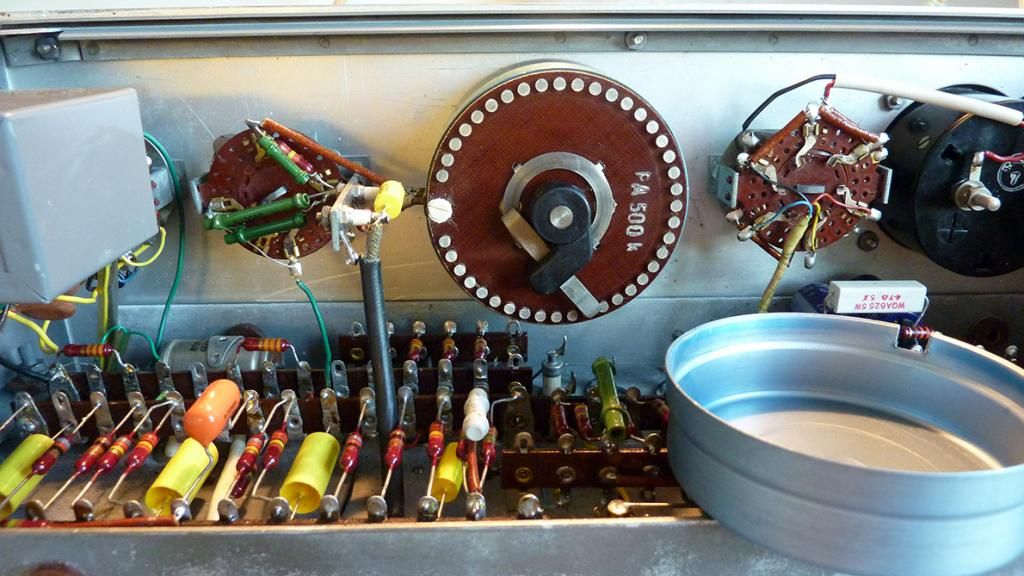
I'm pretty experienced DIYer, but new to tubes, what makes this a little more complicated is that i have no schematic.

So far I have fired up the unit without the cover and noticed that one of the small tubes is not glowing (see pic). i know this is hard without a schematic, but what kind purpose do this sort of tube have generally?

That's where I'm at so far... I have much respect for tubes and the high voltage so if you guys have any good tricks, bring em on!
Next step, follow the signal? Something i should keep in mind when troubleshooting with tubes?

Link to the auction with better pics..
http://www.tradera.com/Mikrofonforstarkare-ror-Radiotjanst-fran-1959--auktion_301973_133076962
 

Attachments

  • IMG_1506small.jpg
    IMG_1506small.jpg
    399.4 KB · Views: 189
Ok, one of the small tubes is definitely broken, there are 3 Raytheon JAN6418 in there, one of them didn't glow, i swapped it with one of the working ones.
Now i need to find a new JAN6418 and hopefully we'll be up and running!
;D

EDIT: Anyone got a good source?
 
and that part looks safe


Hi,

I'd take some time and draw out the schematic, starting with the power supply.  Always be mindful of some basics - 1) make sure the unit is properly fused.  2) make sure it is wired with a 3 prong AC cord with the earth pin connected to chassis. 

A variac with a current meter is a very handy thing to have when testing an old tube unit.  If the PS filtering caps are original be mindful that they could go at any time - short to ground.  A fuse should protect from major damage if this happens.

Once you have the schematic drawn, start checking voltages.  Check the filament voltages first.  These can vary depending on tube type but 6.3VAC is most common. The 6418 will use 1.25VAC. For the plates and cathodes you'd be looking for reasonable voltages.  Without seeing how the tubes are wired it's hard to say exactly what reasonable would be, but for standard RC stages you will have a high (60-300VDC) plate voltage and a low (0.5-5 or so VDC) cathode voltage. 

If you measure zero voltage on one of the tube plates then look for an open resistor in the power supply feed.  If you measure a very high voltage on the plate and zero voltage on the cathode, then look for an open cathode resistor or a poor ground connection at the bottom of the cathode resistor.  These two conditions will = no signal.  A bad tube or no filament voltage will also = no signal.  Also check for broken solder joints or loose connections.

Very nice find! - the VU is a beauty.  I don't see any reason why you couldn't rebuild this as a tube unit of your choice.

Best of luck!
 
Hi!

Did you ever get it working? I happen to have one myself - including the schematic - though it's glued to the inside of the chassis. I suppose I could try to take a photo.
Mine sounds wonderful, but I had to build a power supply myself. Stabilized, 4.5V for the heater & 85V for the anode.

Soundwise I see absolutely no reason to rebuild or mod it.
 
Hi all.

I think I'll have to take back my previous statement (Quote: "Soundwise I see absolutely no reason to rebuild or mod it").

I've been using the preamp alot this summer, and it is noisy. By today's standards, the noise floor is a tad bit too high.
I guess noise wasn't considered that huge of a problem back in the late 50's, but now... well.

These are not gain monsters, like those tube pre's made for telephone lines ;-)

Any quick fixes?

Any input appreciated.
 
Noise performance is usually dominated by the first stage of a mic pre i.e. L1 and L2. You can check this easily. Does the noise go up as you open up the pot R16? If the noise is acceptably low with the pot fully off but too noisy with it up then the first stage is where to focus you attention.

If this is the case then you should check the resistors around the first two tubes. Many of this age used cracked carbon which can become quite noisy over time. Might be worth replacing them with metal film types. The other major source of noise will be the tubes themselves. Not much you can do here except select the one for L1 for lowest noise.

Cheers

Ian
 
Have you measured gain?  If you did, I missed it.  With so many stages, I'd expect noise as normal, even with a new parts build. 
 
Concur.  Anything around 70db or higher is difficult to keep within most modern noise performance models.  I see two pentodes plus two more driving the output and they tend to be inherently hissy.  Also have a large number of switches which can develop noise when the contacts get dirty, and they likely have a good buildup on them by now.
 
Thanks for the input! Much appreciated :)

So... I've now replaced the old 512AX's with NOS Raytheon, a couple of coupling caps and all resistors around the first two preamp stages. New metal film.
The tubes in the output stage are NOS Telefunken's. I guess it's as good as it gets now, tube-wise.

I found a new supply for the heaters, too. A stab pack of some sort, 4.5VDC (up to 15A. Gotta love all those old HAM guys).

Running with my old stabilized tube rectifier:

NEFA_FIX_zps6c8b0bba.jpg


... It's quiet! Well, at least on reasonable levels.

My homebrew B+ supply adds to the noise though. Perhaps I should ditch the FET B+ supply that I've built?
Any alternatives available?
 
> Any alternatives available?

Resistor+Capacitor filtering on the B+??

Always works for me, for stuff that doesn't vary its current demand much.

Hey, it already has filtering! Verify that C4 C8 C13 C15 are good. (Tack a 5uFd 150V electrolytic across each one and see if buzz changes.)

The power-stage expects pure clean battery. Try 220 ohms plus 100uFd between your power-pack and the "battery" input.
 
PRR said:
Hey, it already has filtering! Verify that C4 C8 C13 C15 are good. (Tack a 5uFd 150V electrolytic across each one and see if buzz changes.)

The power-stage expects pure clean battery. Try 220 ohms plus 100uFd between your power-pack and the "battery" input.

Good point! I haven't really checked out the big can caps and the rest of the filtering, so that's the next stop. I guess I thought I could ignore them since the unit is hum-free.

The FET plate supply actually got a 300uF filtering stage, noise supression caps and whatnot. Ideally, it should be a perfect match for the unit, but it seems to add to the noise anyway.

If the cans prove to be bad, does anyone know where to score two 2200uF caps, at least 100WVDC? A little higher margin would be even better.
 
I have found many cases where an additional RC filter between PSU and amp worked wonders.  Go with PRR's suggestion. 
 
Thanks again for the input so far.

So. Now I've tried small caps across each cap in the B+ filtering stage. Unfortunately they didn't make any difference whatsoever.
The large improvement was yesterday: new metal film resistors and, possibly, some of the new coupling caps. It's hard to tell.
It's reasonably quiet now at fairly high gain. At maximum gain it's very noisy, but I don't think I'll ever need that much gain for any microphone/situation.

Cleaning the attentuator (Swedish SELA, high quality!) with isoprop made a coming-and-going pop disappear.
This is before the new metal films:
NEFA-ATTN_zps9f7dd008.jpg


Extras. The Jørgen Schou input transformer:
NEFA-JS_zps1f449121.jpg


I wish Baltazar could fill in at some point. I'm curious how his unit behaves.
 
I couldn't resist posting this, although it has nothing to do with the repair/overhaul:

April-1954-Teknisk-utrustning-i-skogen.jpg


A 2891A in action with a Western Electric 630A hooked up + a pair of Sennheiser DT48's for monitoring.
Dated April, 1954.


B-1957-Eurovision-fran-Drottningholm.jpg

... During the Eurovision Song Contest 1957.
 
> Several successive RC stages with modest R and C values works a lot better than a single RC with big R and big C

Apropos: John Broskie touched on this recently.

http://tubecad.com/2013/08/blog0268.htm

Scroll down-page, he plots a 1-pole (red) and a 5-pole filter (blue) using the same total R and C.

In true Broskie style, the plot runs down to 300 dB (!!).

And the 1-pole is 10K against 235uFd(!!). I remember when 200uFd at tube-voltage was preposterous.

The many-stage is better at 100/120Hz, but MUCH better up in the 400Hz to KHz zone where the ear will really hear it. The steepness of the filter is proportional to the number of stages.

Against that, five 47ufd caps is same-uFd but not the same cost as one 235uFd cap.

(Digi-Key Panasonic: five 47u 400V is $10, one 270u 400V is $4.)

Thanks!! for Scroggie. However even he gets mired.

IMHO, at today's cap prices, you aim for 20dB-30dB per R-C filter stage. Any less tends to be under-filtered (which can also lead you down the motorboating path). Try to get much more per stage, you over-spend and are liable to be defeated by stray parasitic resistance.

So a push-pull output pentode, which can eat 10% ripple raw DC for minor buzz, needs maybe one more R-C to get it dead-clean.

But an input stage with milliVolt signal needs microVolt ripple in its food. Figuring the raw DC has several Volts ripple, we need a million to one attenuation. Or 120dB.

So six stages of 20dB or four stages of 30dB.

How much resistance? How much voltage can you afford to "spend" in filtering, and how much current flows? Langford-Smith suggests as much as 40% voltage-drop in the filter, but caps were much more expensive and he was cheap. In general a 10% drop makes no real difference to a tube, 20% merely means you drop the audio level a bit, and sometimes you just have WAY too much (the 595V Ampegs and their meaty voltage-droppers to 300V preamps).

Somebody said that Resistance is Voltage divided by Current.

With the total resistance, and the number of stages, you have the resistance per stage.

If that resistance is 1K (1,000 Ohms) and you design for 20dB (10:1) per stage, you want a cap reactance of 100 ohms at 100Hz. (120Hz in such lands, but "100" is easier to figure.) Every audio hacker needs to know how to figure capacitive reactance. I used to use Reactance Charts. Later I counted thumbs. Today there's an app for that. 16uFd is 100 Ohms at 100hz. So 1K-16u-1K-16u-1K-16u-1K-16u-1K-16u-1K-16u is a six-stage filter 120dB down at 100hz and 192dB down at 400hz.

For a 30dB per stage design use "30" instead of 10. You will have fewer stages, so the per-stage resistance is more like 1.5K. So you want 1500/30= 50 ohms at 100Hz, or 32uFd. Four stages of that is still 120dB down at 100Hz, "only" 168dB down at 400Hz. But this is still far less than a microVolt and more than good enough.

HOWEVER... I suggested ONE stage just to KISS and get the test done. If Conviction reported "better..." but wasn't there-yet, we'd be on the right track with an obvious path to more happiness. Instead it seems the old-old resistors and caps were much of what he heard, despite the statement that "My homebrew B+ supply adds to the noise".
 
Back
Top