I recently broke down, needing more input channels, and bought an ADA8000 8 channel ADAT interface for use with my portable tracking rack.
Well I was considering the mod's discussed, and whether any of them make sense for me and I discovered that this is a new box, with a new board layout.
From reading the threads I think there are now three versions:
There was the first one with TL074's and i think wavefront converters?
Then there was a version (G) (http://www.inf.ufrgs.br/~johann/ada8000/ADA8000.psu.notes.small.pdf) with the board labeled pcb*516080*REVG/02 - I can't tell if this is the original board or not.
Both had power supply problems due to the transformer feeding too much power to the Regulators. Resulting in regulators burning out, a bad ceramic cap near the rectifier (on the first version, the second apparently made it a film cap) frying and transformer thermal fuse problems. Some report that the bad cap or regulator causes the thermal fuse to blow, like a cascading problem.
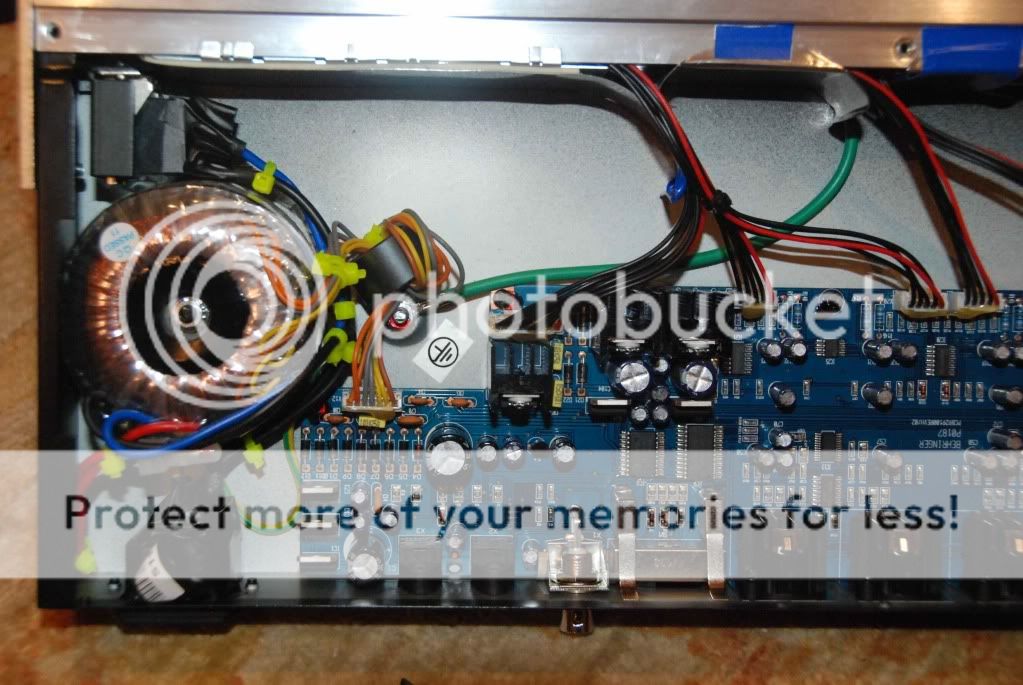
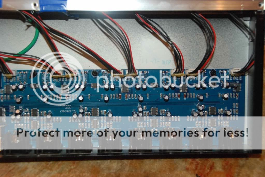
So reporting on the new unit, This is neither of those I think, It has Cirrus converter. The ceramic cap is now film (like on the second unit) the regulators are still too hot to touch, and no additional heat sinking is in evidence. But the odd thing is that main board buffer formerly made up of a quad opamp split between adjacent channels, now seems to be a single chip (8 pads) labeled 072c (which I believe is a TLO72) between each pair of channels, and I cannot figure out the buffer works (are they inverting?) Anyway... it appears there is a rev-H version, still has heat problems (at least I can't touch it, it may not fail i suppose).
Here are the Chips I can read on the main board
Cirrus Logic CS4270-CZZ
ST 074C ( ? TL074 near the output jack)
ST 339 ( ? VU meter LM339)
ST 072C ( ? TL072 positioned between molex pairs where the old 4 way op oamp buffer was)
Wavefront AL1402G (m)
Wavefront AL1401AG
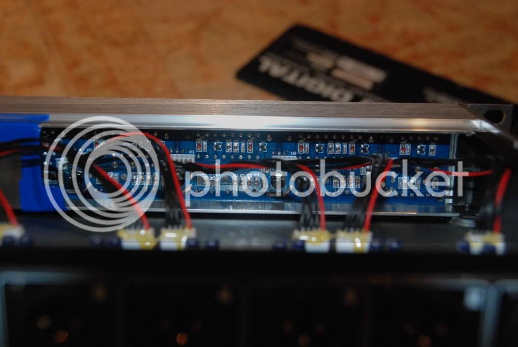
Board is marked B*e*hr... (ignore asterisks)
P*0187 pcb*929100*Rev*H/02
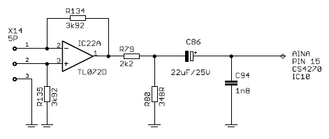
I did look at the Cirrus CS4270 spec and notice that while the wavefront 1101 had a differential inputs, this has single ended inputs. So maybe they don't need to carry a balanced signal on the board and that is why they don't need the second half of that buffer? How would one buffer the Cirrus chip for single ended use? Could I still run a balanced line level signal with appropriate resistors directly to it's non-inverted and inverted inputs?
I did some testing
I could measure hum on the preamps with the gain up some and using digital gain in the DAW.
I measured higher hum (60Hz, 120HZ, and 280ish Hz) on the channels. Worst on channel 8, best on channel 1. I found by adding MU Metal shielding to the back of the front panel (there is a shield there now over channels 8 7 and 6, put probably steel, and I just taped MU Metal over it, but filled in the gaps, extended it some, and added smaller shield further down the front panel. Adding the shield quieted down the channels some.
Note to anyone that has one of these ADA-8000, the front panel is not well shieled, and is very sensitive to the rotation of the transformer.
I loosend the transformer and rotated it while listening to a channel. This makes a HUGE difference, and between that and Shielding I could get channel 8 really quiet (like #1). But it is a tradeoff because 4 and 5 were then the noisiest, and lowering them raises 6, 7, 8 somewhat.
I tried shielding the transformer, unsuccessfully, not much room, and I was worried about creating a shorted loop or heat problems? (how much of a toroid can I contain in shield material without worrying about this "shorted loop" issue? Anybody know?)
Front panel shielding made a big difference and the rotation did even more (although the rotation can fix some bad hum, it also moves hum to other channels) (I got 2 or 3 db lower hum overall off a mix of 8 channels, when I had the hum cranked up to -9 db I got it down to -12 by rotation and shielding. Hum on channel 8 was reduced more dramatically.
If anyone has the schematic for this box, it would be appreciated in the technical documents thread. I would like to do something about the heat and reliability. And I would probably bypass the preamps (to avoid the attenuate-amplify gain stage and associated noise) I just need the converters.
I was thinking of adding some heat sinking, venting , or doing the AC Line Voltage reduction thing (someone did one inside a furman box, which looked good. But I am afraid in a dark venue some night someone (me) will plug something else into the 100 volts .. and kill some other piece of equipment with low voltage)
But if I bypass the preamps and make the line level bypass, I think I can make some brass heat sink extenders for the 5 volt regs that will carry the heat to the top panel of the box, and I think I can turn off the 15 Volts to the front panel if I disable the preamps. That would solve the heat problems (the LM7805 can run on 11+ volts, as long as it doesn't cook)
I think I saw a mod out there with a mic input transformer, and the line level input bypassing the preamp. Or maybe just a transformer isolated line level input. I have a bunch of old Shure, Altec and Beyer transformers from various mixers and preamps and maybe I can work out a way to:
1) Use this as an AD converter only (I don't need the DA)
2) Keep the Sig and Clip LED's intact
3) Turn off the Front Panel 15V and with it - heat hum and hiss.
Anyone know about this rev H board? Have a schematic?
Also noted a tricky little manufacturer thing, Beh...r put a serial number tag on the BOTTOM of a peice of black electricians tape around the IEC power entry module (hey if you burn up a lot of transformers... and regulators... and read the boards... they do! you want to make sure that the customer is returning the right gear and not just swapping the top panel (6 screws lets you swap the serial number to another unit.... so I guess people were buying a replacement, swapping the top cover, and returning it) Anyway, there is a lot of black electricians tape in there, and it is not just sloppy manufacturing, some of it has a purpose! Of course, with the 6 screws off... it is pretty easy to move a piece of electricians tape once you know it is there).
I have pics, if anyone wants I will post them.
Well I was considering the mod's discussed, and whether any of them make sense for me and I discovered that this is a new box, with a new board layout.
From reading the threads I think there are now three versions:
There was the first one with TL074's and i think wavefront converters?
Then there was a version (G) (http://www.inf.ufrgs.br/~johann/ada8000/ADA8000.psu.notes.small.pdf) with the board labeled pcb*516080*REVG/02 - I can't tell if this is the original board or not.
Both had power supply problems due to the transformer feeding too much power to the Regulators. Resulting in regulators burning out, a bad ceramic cap near the rectifier (on the first version, the second apparently made it a film cap) frying and transformer thermal fuse problems. Some report that the bad cap or regulator causes the thermal fuse to blow, like a cascading problem.
So reporting on the new unit, This is neither of those I think, It has Cirrus converter. The ceramic cap is now film (like on the second unit) the regulators are still too hot to touch, and no additional heat sinking is in evidence. But the odd thing is that main board buffer formerly made up of a quad opamp split between adjacent channels, now seems to be a single chip (8 pads) labeled 072c (which I believe is a TLO72) between each pair of channels, and I cannot figure out the buffer works (are they inverting?) Anyway... it appears there is a rev-H version, still has heat problems (at least I can't touch it, it may not fail i suppose).
Here are the Chips I can read on the main board
Cirrus Logic CS4270-CZZ
ST 074C ( ? TL074 near the output jack)
ST 339 ( ? VU meter LM339)
ST 072C ( ? TL072 positioned between molex pairs where the old 4 way op oamp buffer was)
Wavefront AL1402G (m)
Wavefront AL1401AG
Board is marked B*e*hr... (ignore asterisks)
P*0187 pcb*929100*Rev*H/02
I did look at the Cirrus CS4270 spec and notice that while the wavefront 1101 had a differential inputs, this has single ended inputs. So maybe they don't need to carry a balanced signal on the board and that is why they don't need the second half of that buffer? How would one buffer the Cirrus chip for single ended use? Could I still run a balanced line level signal with appropriate resistors directly to it's non-inverted and inverted inputs?
I did some testing
I could measure hum on the preamps with the gain up some and using digital gain in the DAW.
I measured higher hum (60Hz, 120HZ, and 280ish Hz) on the channels. Worst on channel 8, best on channel 1. I found by adding MU Metal shielding to the back of the front panel (there is a shield there now over channels 8 7 and 6, put probably steel, and I just taped MU Metal over it, but filled in the gaps, extended it some, and added smaller shield further down the front panel. Adding the shield quieted down the channels some.
Note to anyone that has one of these ADA-8000, the front panel is not well shieled, and is very sensitive to the rotation of the transformer.
I loosend the transformer and rotated it while listening to a channel. This makes a HUGE difference, and between that and Shielding I could get channel 8 really quiet (like #1). But it is a tradeoff because 4 and 5 were then the noisiest, and lowering them raises 6, 7, 8 somewhat.
I tried shielding the transformer, unsuccessfully, not much room, and I was worried about creating a shorted loop or heat problems? (how much of a toroid can I contain in shield material without worrying about this "shorted loop" issue? Anybody know?)
Front panel shielding made a big difference and the rotation did even more (although the rotation can fix some bad hum, it also moves hum to other channels) (I got 2 or 3 db lower hum overall off a mix of 8 channels, when I had the hum cranked up to -9 db I got it down to -12 by rotation and shielding. Hum on channel 8 was reduced more dramatically.
If anyone has the schematic for this box, it would be appreciated in the technical documents thread. I would like to do something about the heat and reliability. And I would probably bypass the preamps (to avoid the attenuate-amplify gain stage and associated noise) I just need the converters.
I was thinking of adding some heat sinking, venting , or doing the AC Line Voltage reduction thing (someone did one inside a furman box, which looked good. But I am afraid in a dark venue some night someone (me) will plug something else into the 100 volts .. and kill some other piece of equipment with low voltage)
But if I bypass the preamps and make the line level bypass, I think I can make some brass heat sink extenders for the 5 volt regs that will carry the heat to the top panel of the box, and I think I can turn off the 15 Volts to the front panel if I disable the preamps. That would solve the heat problems (the LM7805 can run on 11+ volts, as long as it doesn't cook)
I think I saw a mod out there with a mic input transformer, and the line level input bypassing the preamp. Or maybe just a transformer isolated line level input. I have a bunch of old Shure, Altec and Beyer transformers from various mixers and preamps and maybe I can work out a way to:
1) Use this as an AD converter only (I don't need the DA)
2) Keep the Sig and Clip LED's intact
3) Turn off the Front Panel 15V and with it - heat hum and hiss.
Anyone know about this rev H board? Have a schematic?
Also noted a tricky little manufacturer thing, Beh...r put a serial number tag on the BOTTOM of a peice of black electricians tape around the IEC power entry module (hey if you burn up a lot of transformers... and regulators... and read the boards... they do! you want to make sure that the customer is returning the right gear and not just swapping the top panel (6 screws lets you swap the serial number to another unit.... so I guess people were buying a replacement, swapping the top cover, and returning it) Anyway, there is a lot of black electricians tape in there, and it is not just sloppy manufacturing, some of it has a purpose! Of course, with the 6 screws off... it is pretty easy to move a piece of electricians tape once you know it is there).
I have pics, if anyone wants I will post them.
")