Non-gapped output-TX with DC... and 'counter-magnetizing' ?!

GroupDIY Audio Forum

Help Support GroupDIY Audio Forum:

This site may earn a commission from merchant affiliate links, including eBay, Amazon, and others.
I saw the LA-3A is using around 10mA of 'counteracting'.
Since they simply use the double value of R16 for R20 they're probably
leaving some (fractions of) mA worth of DC-magnetizing
uncompensated for.

AC-wise, I realized there's feedback going on by
attaching the lower side of that R16 / 1k2 to the
output-primary.
 
Thanks. Yep, the ratio wil remain the ratio ! :wink:
I should measure it and then it can be frozen into the
ratio w.r.t. the 47 Ohms resistor above.
You're right, there is no need for a servo - and if there
was it would have been difficult indeed.

So I'd say make sure about this winding ratio,
and then make sure that your compensation current
will follow all the possible electronic drifts inside your circuit.
Looks like the drawn VCCS-circuit is still suited.

The VCCS (with added LPF)
You're thinking of a LPF before the non-inv. input of the opamp ?
Hmm, probably not there, since AC across the 47 Ohms is already
taken care for by the electrolytic.
Do you have a suggestion ?

Regards,

Peter
 
The VCCS (with added LPF)
You're thinking of a LPF before the non-inv. input of the opamp ?
Hmm, probably not there, since AC across the 47 Ohms is already
taken care for by the electrolytic.
Do you have a suggestion ?

Ah, I didn't notice the electrolytic. So there is some LPF function on that node already. Well, I'd really have to look at the whole circuit (again) to see what else is connected there, before I try giving any advice. But let's see, even with just the 47Ohms and the 80uF, the corner frequency is a bit high for DC compensation (calculates to 42Hz), and the emitter of the 3055 will certainly make it even more low-impedance, raising the corner frequency.

Anyway, can't hurt to add a RC-filter before going to the opamp, resistance high enough not to interfere with the amp (10k should be fine), and a cap to fit your desired roll-off frequency.

The good thing about this _not_ being a servo is that you can add poles without getting stability issues!

What I really don't know (and maybe I should ask this in a different, "newbie" thread!):
What *is* a good corner frequency for an audio transformer to protect against DC, in general ?? (Not just speaking of compensation; also speaking of ordinary DC blocking with a capacitor.)
For an uncompromised low end, I'd set the corner frequency as low as possible. But if it takes 10 seconds for the currents to be settled after turn-on or after plugging something in, will this long transient be as hurtful as "real" DC?

JH.
 
from Juergen:
Ah, I didn't notice the electrolytic. So there is some LPF function on that node already. Well, I'd really have to look at the whole circuit (again) to see what else is connected there, before I try giving any advice.
The 80uF elco is drawn a bit unusual in the BA283 schematic, and it's in fact in series with the supply-decoupling (but that one will likely be a lot larger in value).

But let's see, even with just the 47Ohms and the 80uF, the corner frequency is a bit high for DC compensation (calculates to 42Hz), and the emitter of the 3055 will certainly make it even more low-impedance, raising the corner frequency.
That's true, hadn't realized. Could use more uFs here.

Anyway, can't hurt to add a RC-filter before going to the opamp, resistance high enough not to interfere with the amp (10k should be fine), and a cap to fit your desired roll-off frequency.

The good thing about this _not_ being a servo is that you can add poles without getting stability issues!
Right ! Wouldn't hurt to add something with a filmcap, in case (just in case) the elco doesn't s*ck all higher freqs...

What I really don't know (and maybe I should ask this in a different, "newbie" thread!):
What *is* a good corner frequency for an audio transformer to protect against DC, in general ??
Good question ! Maybe the MoMetal-thread gives a clue.

For an uncompromised low end, I'd set the corner frequency as low as possible. But if it takes 10 seconds for the currents to be settled after turn-on or after plugging something in, will this long transient be as hurtful as "real" DC?
These seem relevant concerns ! :roll: :cry:
I have no idea but we should try to understand this.
Could something be derived from the 'strange observations' in the MoMetal-thread ?
It'll hit one TX probably harder than others, but there wiull be a general mechanism I suppose.

Bye,

Peter
 
All right, as we're waiting for the experts to tell us about low frequency treatment of transformers, I'll give that 80uF and its implications a try:

[quote author="clintrubber"]from Juergen:
Ah, I didn't notice the electrolytic. So there is some LPF function on that node already. Well, I'd really have to look at the whole circuit (again) to see what else is connected there, before I try giving any advice.
The 80uF elco is drawn a bit unusual in the BA283 schematic, and it's in fact in series with the supply-decoupling (but that one will likely be a lot larger in value).

But let's see, even with just the 47Ohms and the 80uF, the corner frequency is a bit high for DC compensation (calculates to 42Hz), and the emitter of the 3055 will certainly make it even more low-impedance, raising the corner frequency.
That's true, hadn't realized. Could use more uFs here.
[/quote]

If you look at the just the output stage (darlington - i'll refer to it as 3055 for simplification), without the feedback loop, that's a voltage controlled current source, described by some gm factor. *With* the feedback loop (from the collector of the 3055 back to the emitter of the input transitor), this becomes a voltage output more or less, and variations of the gm will more or less be evened out, as in any tight feedback circuit.

But let's look at the open loop behaviour for a moment longer.
The 3055 with it's emitter tied to GND would have a rather high gm, depending on its internal emitter resistance, which in turn depends on the emitter current. An external emitter resistor will degrade the gm. So for getting a high gm despite the resistor that is needed to set the DC bias, the external resistor is bypassed by a capacitor. In this circuit, the capacitor is way too small to make a bypass at low and even mid frequencies (still talking of open loop mode.)

The feedback loop evens this out, so you get the desired over-all wide band response. But this has two consequences:
(1) I'd expect distortion to rise at lower frequencies (even without the transformer!), which might be part of that special character of the circuit. But I'm not sure about that, so I won't speculate any further here. But the other thing is quite obvious:
(2) when the gm of the 3055 falls with lower frequency, and the overall voltage gain and load impedance stay fairly constant, you'll get an increasing amount of AC signal at the 3055's emitter, too.

To quantify this a bit, at roughly 4Hz, the emitter shows the same audio level as the collector. At 100Hz, the emitter signal is approx. 23dB weaker than the collector. At 16Hz, it's only 8dB.

I have no idea if this is "good enough" to be directly used for a compensation VCCS, but I'd be prepared that it might slightly alter the sound. (Remember that additional signal path is no discrete NEVE circuit anymore, it's whatever the opamp you choose will make out of it.

If I were you, I'd put in an extra filter.

JH.
 
Hi,

OK, sensing the DC across the 47 Ohms resistor seemed
straightforward but no longer so.
So better be save than sorry indeed and adding that
additional filter - no problem.

Or give up on the automatic compensation - once the
circuit-biasing is adjusted it's just another ten seconds
to trim an counteracting-current, which is then no
longer anywhere sensing the BA283-circuit.

When using a separate supply-voltage (for less waisted
power, but higher component count) it'd could even be
without any opamp at all. Or there will be an easy
possibility with a LM317+trimpot.

Or even simpler just make it a trim (should be able
to carry lot's of mA's) or trim&measure&replace with
a fixed resistor (the LA-3A style).

And thanks for that analysis ! - should catch a train now,
will have a further look at it.

Bye,

Peter
 
Hi CJ,

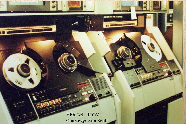
Ampex x-formers out of a 351?
No, they're from a VPR-2B 'video production recorder'.

Ampex-VPR-2B.jpg

(this is a googled pic, not the unit I got them from since the remains
of that one will be have been trashed by now)

I have some more pics of the TX-board, the schematics &
questions about these, but skipping the input stuff for now.

That TX-board has 4 of such outp-TXs, 3 line input-TXs and 1 mic-input-TX.

FWIW, outp-TX-'circuit' is like this, about a 1:2.5 Prim to Sec ratio.
TX-out_sch.jpg

Ratio of Prim:Tert not measured yet. The Tert is originally driving the
meter-circuit and is now targeted for taking the counteracting DC.

Bye,

Peter
 
Cool. Those x-formers might be the same ones used in the 351. M6 with really good sound, thousands of hit records went through the 351 iron.
 
from CJ:
Cool. Those x-formers might be the same ones used in the 351. M6 with really good sound, thousands of hit records went through the 351 iron.

Sounds good ! Did some googling for a 351 circuit
but got the impression that one uses a 15k:600 ?

The TXs I have are following an output-stage with
basically an opmap ('540) and two discretes, so low-Z.

FWIW, dimensions of the TXs I have are:
1.53 * 1.8 * 0.59 (the iron itself, H*W*D, inches).

They're marked '4580067-02' & T2603-B,
where the former stands for the Ampex part-no
but I have no idea what 'T2603-B' is indicating.
Type-info from the eventual original manuf. ?

Sorry, not read enough on TX-stuff yet
- 'M6' is describing the core-material ?

Bye,

Peter
 
from NYD:
Ha! We just got rid of some VPR-2s where I work. I didn't even think of cannibalizing them for parts before they went to the scrap heap...
:cry: I'm sorry to hear that. :sad:
I saw that thing and got it rid of it's XLR I/O-connectors
but then only later thought about the possible presence
of some TXs.

While I guess it probably won't be that special
what I got here, I won't be posting additional pics here
to avoid additional discomfort at your side.

OK, just this one; these are the line-input-TXs and I'm
actually a bit puzzled about what they're doing here
since they're using a series connection of 25k,
TX-prim and 25k and the sec directly drives a
virtual earth.
Probably these TXs can't take the complete
line-inp strength.
But I'll better post in a separate thread & with a schematic.

TX-in_pic11.jpg

BTW, that little one in front seems a Beyer, it's for the mic-input.

Bye,

Peter
 
from Juergen:
All right, as we're waiting for the experts to tell us about low frequency treatment of transformers, I'll give that 80uF and its implications a try:

If you look at the just the output stage (darlington - i'll refer to it as 3055 for simplification), without the feedback loop, that's a voltage controlled current source, described by some gm factor. *With* the feedback loop (from the collector of the 3055 back to the emitter of the input transitor), this becomes a voltage output more or less, and variations of the gm will more or less be evened out, as in any tight feedback circuit.

But let's look at the open loop behaviour for a moment longer.
The 3055 with it's emitter tied to GND would have a rather high gm, depending on its internal emitter resistance, which in turn depends on the emitter current. An external emitter resistor will degrade the gm. So for getting a high gm despite the resistor that is needed to set the DC bias, the external resistor is bypassed by a capacitor. In this circuit, the capacitor is way too small to make a bypass at low and even mid frequencies (still talking of open loop mode.)
're' would be 25mV/70mA, but couldn't find the fixed part of the internal 2N3055 emitter resistance in the datasheet I had.
OK, for now let's assume total re is below a few Ohms.

The feedback loop evens this out, so you get the desired over-all wide band response. But this has two consequences:
(1) I'd expect distortion to rise at lower frequencies (even without the transformer!), which might be part of that special character of the circuit. But I'm not sure about that, so I won't speculate any further here.

That's interesting. This should be measurable. Anyone did happen to do some BA283-THD-measurements at some various frequencies before perhaps ? Once I've finished a board I'll measure.

But the other thing is quite obvious:
(2) when the gm of the 3055 falls with lower frequency, and the overall voltage gain and load impedance stay fairly constant, you'll get an increasing amount of AC signal at the 3055's emitter, too.
I should think more about this - it'll mean that the 47 Ohm resistor is likely swamped by the 2N3055 internal impedance and doesn't play a role anymore (actually at all, it never did) in the lower corner frequency.

To quantify this a bit, at roughly 4Hz, the emitter shows the same audio level as the collector. At 100Hz, the emitter signal is approx. 23dB weaker than the collector. At 16Hz, it's only 8dB.
I tried to place those figures but 23 & 8 don't directly sound like back-of-envelope values :wink: - you did some further calculations or a simulation ?

The previous thing you mentioned w.r.t. power-on magnetizing is still 'worrying' me. Quick jump in RDH brought nothing. It'll be doable to sense more accurately the exact DC through the TX-primary - I figure we need to (actively) mimic/copy the switchon-transient into the counteracting winding...

... and simply assume we're not playing at the same time we're switching the unit on. So no or less AC-filtering required then, but this all is quickly becoming more complex than one should wish since later on we do need the filtering again - or we should rely on the class-A nature of the circuit and derive the prim-DC from there.

But in general, it'll be a more or less elaborate fix for a problem that might not exist altogether...
The separate thread you suggested is a good idea, I'll post.

Bye,

Peter
 
[quote author="clintrubber"]
I tried to place those figures but 23 & 8 don't directly sound like back-of-envelope values :wink: - you did some further calculations or a simulation ?
[/quote]

Simulation. Simplified (different transitors and idealize transformer), but quite good for things like that. I could only guess the direction from looking at the circuit, but never quantify it without Spice.

JH.
 
Hi Juergen,

Simulation. Simplified (different transitors and idealize transformer), but quite good for things like that. I could only guess the direction from looking at the circuit, but never quantify it without Spice.
I see, thanks.

I've been thinking a bit about how to mimic the switch-on DC-current in the primary and haven't found much usable possibilities.

It'd be easy to realize some soft switch-on in the compensating winding but we're in the mist about the required accuracy.
One could take no risks and determine the switch-on behaviour (one shot scope pic) and faithfully reproduce & scale that for the compensating winding but it might be overkill.

Bye,

Peter
 
Holy cow I was bummin around for a schematic for Keef and low and behold, I think I found a DC current compensating scheme for a tube amp at least.
Check this out:

http://www.waltzingbear.com/Schematics/RCA/BA-3C.htm
 
Interesting find ! :thumb:


The 3-1 winding of T-2 ?

Hmm, looks like meant for feedback, but I'm curious if
they had 'DC-ideas' as well or just take that for
granted in this winding.
I guess the DC through winding 6-4 will be a lot more.
So unless the ratios scale enough I wonder if there's much
DC-current compensating ?

Bye,

Peter
 
Darn, it is just a feedback winding.
One end goes to ground ant the other to the cathode. I see no DC.
Oh well. Back to the drawing board. :razz:
 
Darn, it is just a feedback winding.
One end goes to ground ant the other to the cathode. I see no DC.
Oh well. Back to the drawing board.

Hey, there is DC thru that winding ! :wink:

It'll be small though. For some reason I was thinking
(wanting to think ?) that V2 was a CF, so lots
of VDC on its cathode. But no.

Juergens LA-3A find was spot on, this was definitely
compensation. So it's being done.

Bye,

Peter
 

Latest posts

Back
Top