Harrison Ford Filter Feeler

GroupDIY Audio Forum

Help Support GroupDIY Audio Forum:

This site may earn a commission from merchant affiliate links, including eBay, Amazon, and others.
emrr said:
Here's a bit of esoterica for all to consider.  When coupled with INA137 or THAT 1246 (-6 dB).

DRV134: unity gain driving 600 ohms.  +0.7 dB driving 10K.
THAT1646: unity gain driving 10K.  -0.7 dB driving 600 ohms. 

In other words, both are +6 dB parts characterized for different loads, even though they are considered interchangeable. 

May make a difference to you, may not.  Important to grasp that a hard bypass of either system is still not likely a matched gain comparison.
? So they seem interchangeable and both suffer from same 0.7dB level drop with higher load that a hard bypass would leave unchanged.
 
Both are characterized as +6 parts, but one is +6 into 10K ohms, the other +6 into 600 ohms.
 
Hey, just want to know if I built my filters correctly, or if i did something terribly wrong.  2 issues.
1) theres a ton of added gain through the units.
2) the bypass switch works kind of opposite the way id expect (pushed in means ON not bypass).

They sound AMAZING, so im not complaining (much) just wanna figure out if i messed something up or not.
 
I'd guess you are probably almost 7 dB up, so swapping input IC and loading the DRV output with 600-700 ohms should get you to unity.  If you have a THAT part in the output, it's fine unloaded. 
 
sorry im terrible at this, when you say load the output are you just talking harware impedance (like mic pre impediance) or is there a resistor that needs to be changed on board.
 
If you used the DRV output part, a 600-700 resistor added across the output + and - will do it, when feeding 10K+ input devices.  If you used the THAT part it's fine.  There's no place onboard for that resistor.  The input chip is the bigger deal.  Measure your actual gain as-is now to confirm what I'm expecting.

#2) it's designed as button out = bypass.  Intuitively it's an 'on' button rather than a 'bypass'.
 
Hey, I'm going to start a wtb thread but if anyone has any spare pcbs could they please pm me.
Thanks.
Matt.
 
Dudes, am I crazy or is this thing +6 in both bypass and on?  It is!  (that would be +7.5 at the Chebychev ripple points)
on:
INA134 (unity) -> R1/R2/IC1A (-6) -> HPF (+6) ->LPF (unity) -> DRV134 (+6) = +6dB
bypass:
INA134 (unity) -> DRV134 (+6) = +6dB
Put INA137 or THAT1246 in the input to have unity throughput. Or am I crazy?
I can't quite believe it got missed, but I sure don't see it addressed anywhere in the thread, or the related threads. 

Nice work, Doug. 
So a  INA137 or THAT1246 on the input gives unity gain (instead of INA134, which is +6dB).

Those 134 chips are expensive - maybe the BOM on the first page could be updated?
 
minor_glitch said:
Quick photo of work in progress.  Everything seems to fit nicely.  Now on to the psu, wiring, etc...

8264122744_b59b3144cf.jpg

Hi!

That looks great! How did the wiring go?

I've only built a couple of preamps for my luchbox so I'm a bit puzzled about the psu and wiring process. Would be nice to see some finished units.

Peace!
 
Looks great!

I wanted to let you guys know I am going to start stocking pots and knobs for these.  That will make it much easier.  Once I get those in I may do full kits. 

The Knobs and Pots are ordered!
 
dandeurloo said:
Looks great!

I wanted to let you guys know I am going to start stocking pots and knobs for these.  That will make it much easier.  Once I get those in I may do full kits. 

The Knobs and Pots are ordered!
Cool. I had problems finding the right knobs. Using 6,3mm for the 6mm shafts I belive. Not pro, but works :)
 
I'd like to mod the filters.

From post #199 I read that
with the 47k pots
Lo-cut is something like 58-4k Hz
Hi-cut is something like 120-14kHz

Now, what I'd like is
Lo: 20hz-1k4Hz (divided by 3)
Hi: 240-2k8hz (multiplied by 2)
or something along those lines.

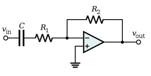
The highpassfilter is a dual 12db/oktave aktive filter, right?

7d87bc118166402407c6194a521f4eac.png


and Highpass#1 is determined
by R3 (390) and pot (0-47k) and cap C2 (0,1u)?
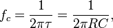
So, fc_min = 1/(2 * pi * 390 * 0 * 0,1 * 10^-6) = 0,08 ??
So, fc_max= 1/(2 * pi * 390 * 47000 * 0,1*10^-6) = 4080

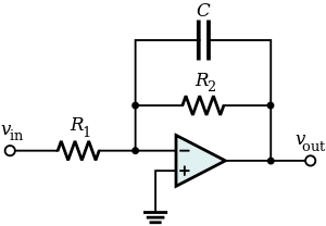
and for lowpass (the same formula)
c5 (0,047u) R4 (390) and pot (0-47k)
fc_max = 1/(2 * pi * 390 * 0,047*10^-6) = 8682 ??
fc_min = 1/(2 * pi * 390 * 47000 * 0,047*10^-6) = 0,18 ??

My calculations seems of, yet the odd thing is hipass fc_max. It seems right..

So, either I need to change some resistors (R3, R4, R5, R8) or
some caps (C2, C3, C4, C5), right?


Seems like the capacitors are easiest to change.

So, for highpass:
C_new = C_old * 3 = o,1uF * 3 = 0,3uF
(So, 0,33is the value to look for, right?)

and for lowpass:
C_new = C_old / 2 = 0,047uF / 2 = 0,0235uF = 23,5nF
(I guess 0,022uF then maybe)

Edit: I need some help here. It seems like I don't understand the components involved or the curcuit.
Checked C3 and C4 and they are not identical to C2 and C5. hmm.. ??
These are 12db, filters, right? And the dual pots are because the filters are doubled, right (vs. 6db/oct)?

I guess this is the right diagrahm for the highpass-filters:
300px-Active_Highpass_Filter_RC.png


And this is for the lowpass-filter:
300px-Active_Lowpass_Filter_RC.svg.png

I presume (from wikipedia)
 

Latest posts

Back
Top