


gemini86
Well-known member
In October 2011, a friend of mine and local studio owner had an interest in building some 9K pres and we went about pricing out the build, and then I remembered that he has an API 200 rack with only 4 spaces being used, so I offered to design some PCBS for him to fill the thing up and save building another case.
This meant fitting everything on-board, and adding the little go-between extras needed to complete the preamp. Some forum members expressed interest, so here we are, the SSL 9K2 for mass consumption:
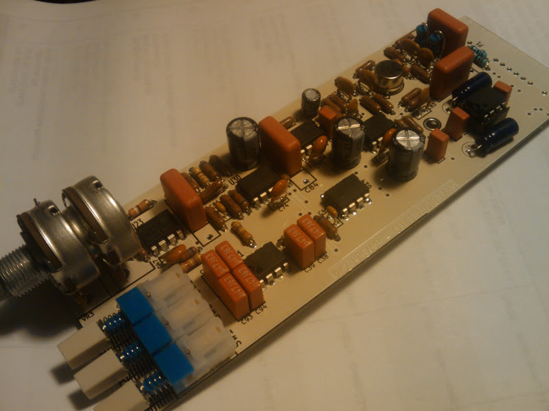
Features input pad, phase and phantom on board, balanced output using THAT1646 IC. Runs on +/-16V
The BOM is as follows:
+48 1 "SW1"
100K 6 "R70, R78, R106, R114, R120, R123"
100n 2 "C1, C45,C2, C3" ((2.5MM lead spacing))
100p 4 "C56, C61, C70, C86"
100R 4 "R5, R57, R72, R108"
10K 1 "R112"
10p 1 "C48"
10u/25 1 "C72"
120R 1 "R8" ((for 20dB pad-shunt))
15uH 2 "L1, L2" ((the little ones that look like resistors))
THAT1646 1 "U1"
1K 4 "R73, R88, R109, R115"
200R 2 "R75, R110"
220u/25 3 "C34, C62, C92"
22uF 2 "C4, C5" ((non-polar/bipolar electrolytics for 1646 sense circuit))
27R 1 "Ra1"
2K5 R/LOG 1 "VR3" ((from audiomaintenance.com))
2U2/63 4 "C55, C68, C69, C84" ((10 or 15MM lead spacing))
300R 2 "R71, R107"
330p 4 "C57, C58, C71, C82"
39R 1 "Rb1"
3K9 2 "R69, R105"
3p3 4 "C46, C47, C73, C74"
470k 3 "R82, R118, R119"
470n 6 "C38, C39, C64, C65, C93, C94" ((5MM lead spacing))
470p 2 "C59, C83"
470R 2 "R6, R7" ((for 20dB pad-series legs))
47R 2 "R76, R77"
4K22 1 "R113"
50K 2 "R81, R117"
6K8 6 "R83, R84, R121, R122"
6K81 2 "R1, R2" ((precision matched for phantom power))
MAT-02 1 "Q5" ((from forum member Electrochronic))
NE5534N 5 "U22, U23, U24, U29, U30"
PAD 1 "SW2"
PH 1 "SW3"
TL072 1 "U31"
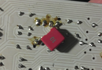
All switches are ALPS SPUJ series DPDT or equivalent. I added another 100nF cap to the underside of the PCB directly under the PCB pins of each IC, but that is likely not needed. This will be added to future revs if the need arises.
This meant fitting everything on-board, and adding the little go-between extras needed to complete the preamp. Some forum members expressed interest, so here we are, the SSL 9K2 for mass consumption:
Features input pad, phase and phantom on board, balanced output using THAT1646 IC. Runs on +/-16V
The BOM is as follows:
+48 1 "SW1"
100K 6 "R70, R78, R106, R114, R120, R123"
100n 2 "C1, C45,C2, C3" ((2.5MM lead spacing))
100p 4 "C56, C61, C70, C86"
100R 4 "R5, R57, R72, R108"
10K 1 "R112"
10p 1 "C48"
10u/25 1 "C72"
120R 1 "R8" ((for 20dB pad-shunt))
15uH 2 "L1, L2" ((the little ones that look like resistors))
THAT1646 1 "U1"
1K 4 "R73, R88, R109, R115"
200R 2 "R75, R110"
220u/25 3 "C34, C62, C92"
22uF 2 "C4, C5" ((non-polar/bipolar electrolytics for 1646 sense circuit))
27R 1 "Ra1"
2K5 R/LOG 1 "VR3" ((from audiomaintenance.com))
2U2/63 4 "C55, C68, C69, C84" ((10 or 15MM lead spacing))
300R 2 "R71, R107"
330p 4 "C57, C58, C71, C82"
39R 1 "Rb1"
3K9 2 "R69, R105"
3p3 4 "C46, C47, C73, C74"
470k 3 "R82, R118, R119"
470n 6 "C38, C39, C64, C65, C93, C94" ((5MM lead spacing))
470p 2 "C59, C83"
470R 2 "R6, R7" ((for 20dB pad-series legs))
47R 2 "R76, R77"
4K22 1 "R113"
50K 2 "R81, R117"
6K8 6 "R83, R84, R121, R122"
6K81 2 "R1, R2" ((precision matched for phantom power))
MAT-02 1 "Q5" ((from forum member Electrochronic))
NE5534N 5 "U22, U23, U24, U29, U30"
PAD 1 "SW2"
PH 1 "SW3"
TL072 1 "U31"
All switches are ALPS SPUJ series DPDT or equivalent. I added another 100nF cap to the underside of the PCB directly under the PCB pins of each IC, but that is likely not needed. This will be added to future revs if the need arises.
")