My first CNC Routed PCB

GroupDIY Audio Forum

Help Support GroupDIY Audio Forum:

This site may earn a commission from merchant affiliate links, including eBay, Amazon, and others.

etheory

Well-known member
Joined
Mar 21, 2011
Messages
604
Location
Sydney, Australia
Hi there!

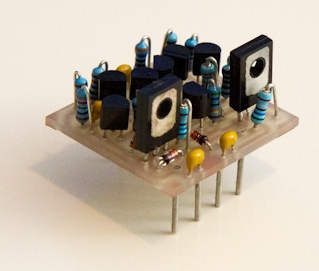
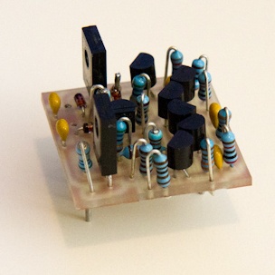
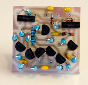
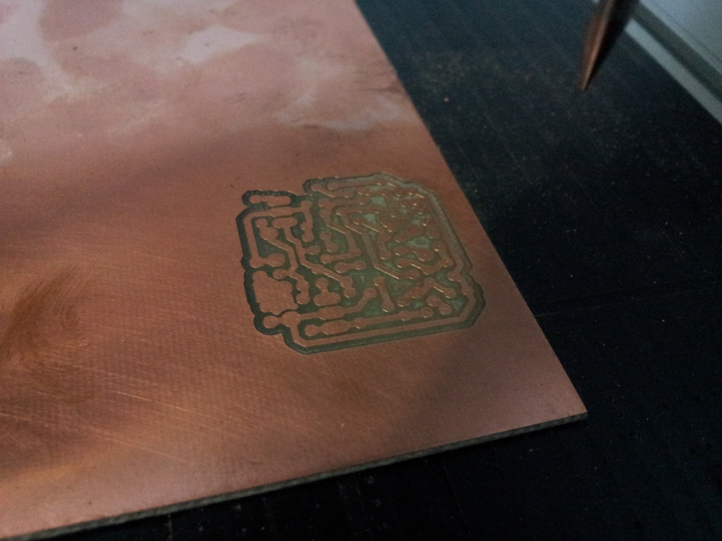
I spent some of today using a CNC machine for the first time to create my own PCB.
I started with a single-sided board layout that I did from scratch of an API2520-style circuit in Eagle, based on some LTSpice simulations I did of the circuit.

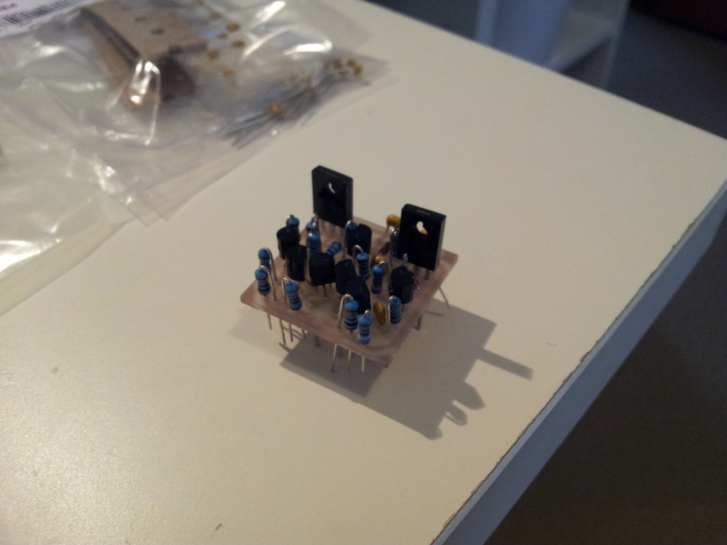
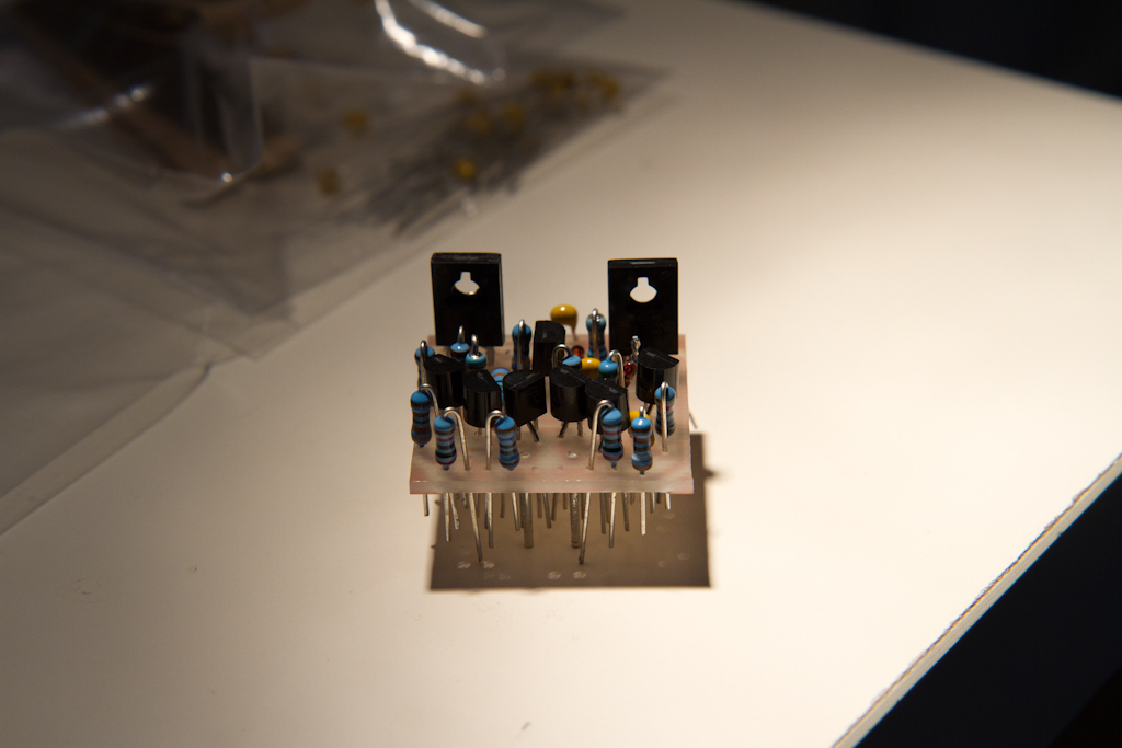
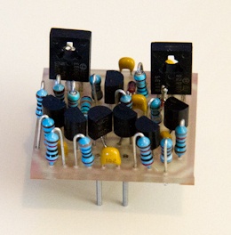
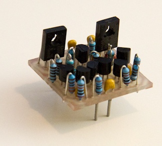
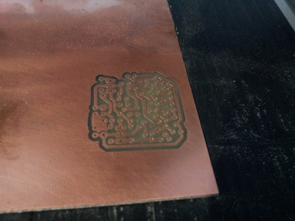
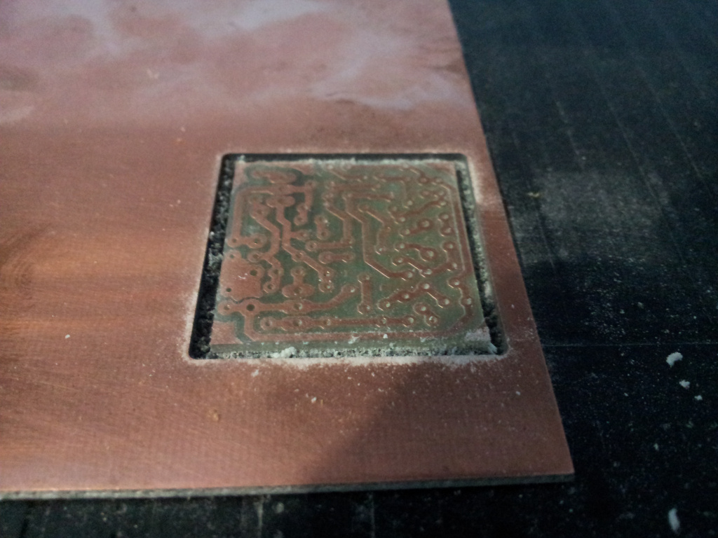
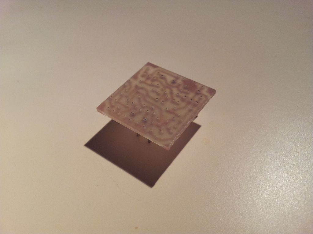
Here are some images of the process:
2011-12-17-18.38.27_small.jpg

2011-12-17-18.57.56_small.jpg

2011-12-17-19.06.36_small.jpg


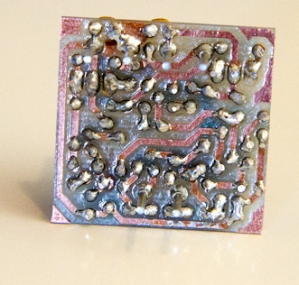
And here is the final board ( as yet unpopulated or tested, so I will expect it to fail and explode with pink smoke or something when I first switch it on ;-) ):
2011-12-17-20.38.43_small.jpg

2011-12-17-20.38.54_small.jpg

2011-12-17-20.39.43_small.jpg


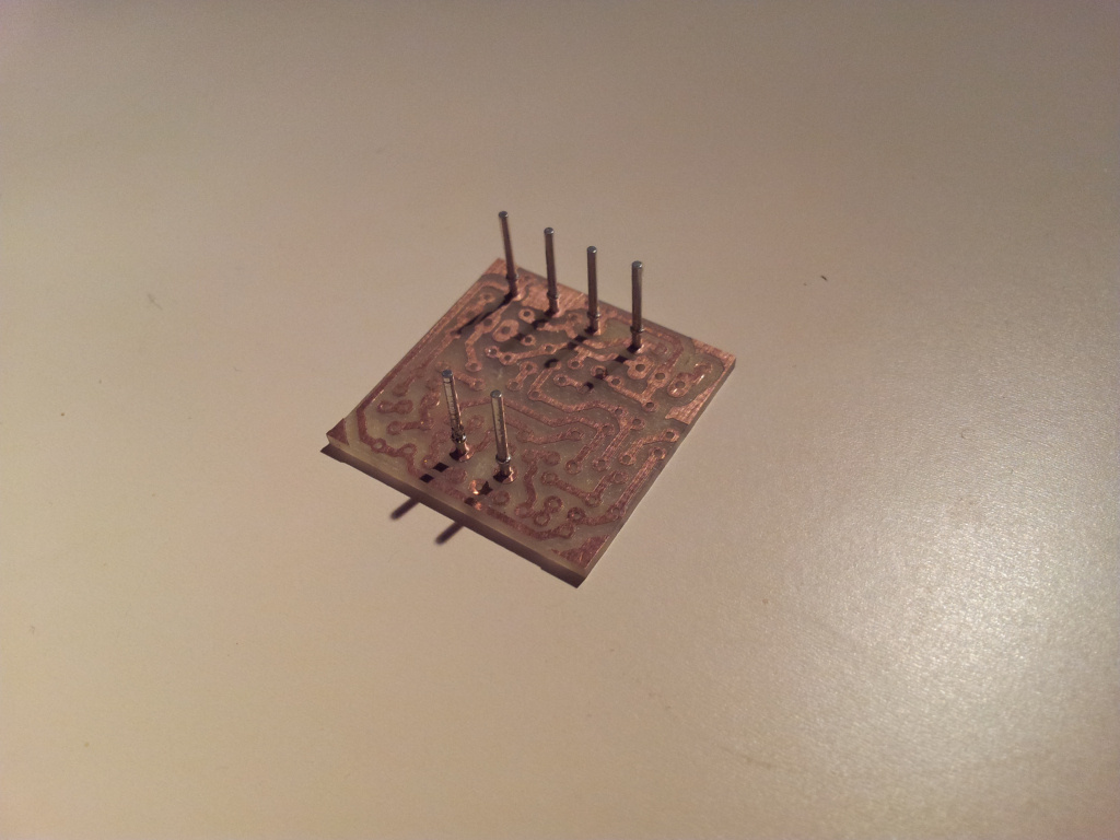
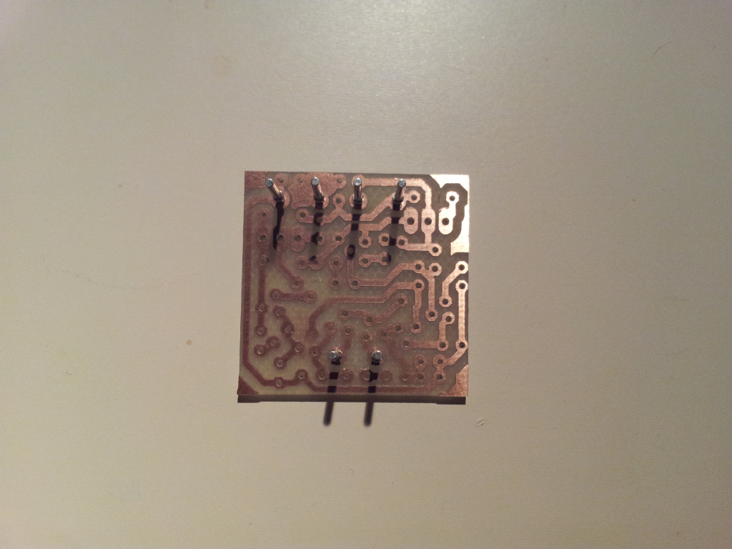
It was loads of fun, fast, cheap, and will allow me to iterate through my designs quite quickly, which I am looking forward to.
If you have access to a space with a CNC machine definitely give it a go - it's a GREAT technique for prototyping.

I'll keep you all posted on the progress of the DOA too.  I am quietly confident it'll "just work" when I first try it, but you never know!
Either way it'll be a valuable learning experience.
 
zayance said:
Nice job, how much time for achieving this?

Not sure which part of the process you mean so I'll be verbose ;-)

1.) The circuit creation and verification in LTSpice - 1.5 Days, including various loading tests, frequency response tests, harmonic series calculations for distortion estimates and stability testing.

2.) Schematic copying into Eagle PCB v6.0 ( the freeware version ) - about 3hrs.

3.) Generating a set of custom parts, footprints, and symbols in LTSpice to match the precise part sizes and specifications I ordered - about 1.5Days ( but it's amortized since I won't have to do it again for BC550C or BC560C transistors or the BD139 and BD140 transistors ) - as dealing with the library functions in Eagle is hell on earth until you grow accustomed to it's "quirks".

4.) Layout of the board - this was D I F F I C U L T - do NOT underestimate this - since it's a completely manual process ( I never use the auto-routing as it sucks ).  Especially when you run before you can crawl like me.  This was about 3 late nights of head scratching, but now I think I could do this in a day with reasonable efficiency.  It's a thing you eventually just "get".  I did stuff like mess with the footprints of the transistors to get them to fit into the tiny tiny space you have to work in ( about 3cm x 3cm ).

5.) Generating the gcode - I use an addon .ulp for Eagle called pcb-gcode-setup.ulp ( I can't remember where I got it from but I'll find out for you ) that does all that work automatically - about 2mins.

6.) The "etching" layer on the PCB - about 30mins
7.) Drilling layer - about 10mins
8.) Milling layer - about 2mins

I could improve that speed via a number of different options, but since it was my first CNC'ed board and I have a lot to learn, I'll adjust feed rates and bit sizes to get the best finish vs time ratio.  The bit I used was a pointed 0.2mm etching bit.  The drills were 0.7mm, 0.8mm and 1.0mm for the holes and the milling bit was 2mm.
 
MicDaddy said:
  Brilliant!  Really nice job  :)

What cnc did you use? 

My wife has a pair of cricut machines I've been eyeballing.  8)

Your wife sounds awesome!  I wish my girlfriend had a pair of cricut machines around the house!  They would be really useful for photo-etching....

The CNC I used was at a Sydney Hackerspace: http://robodino.org/define-hackerspace called Robots and Dinosaurs: http://robodino.org/.

So I am not sure about exactly which machine it is.  I can ask them and write back when I find out.
 
I was talking about the Milling, drilling process, but thanks for the detailed Infos...

BTW, very cool idea of sharing space, that RoboDino Place....
 
zayance said:
BTW, very cool idea of sharing space, that RoboDino Place....

It's an amazing space to have access to for sure.
There is also a laser cutter/engraver here, lab PSUs and analog oscilloscopes etc. etc. - a heavenly place to build stuff!

If anyone from this forum ever finds themselves in Sydney or indeed already lives here let me know by sending me a PM.  I would be happy to show you around the space.

 
really cool!! can't wait to start the fabacademy course i just enlisted in to start with their (shopbot) cnc and (roland) pcb machines.

btw the milling looks really clean. Most of the roland milled pcb's i've seen had burred edges. Not like a good clean photo etch.

greetings,

Thomas
 
hobiesound said:
really cool!! can't wait to start the fabacademy course i just enlisted in to start with their (shopbot) cnc and (roland) pcb machines.

btw the milling looks really clean. Most of the roland milled pcb's i've seen had burred edges. Not like a good clean photo etch.

greetings,

Thomas

The key is to go slowly.  Basically if the milling bit moves too fast, there is not enough time to fully remove the material, and you actually see the bits "bite marks" going into the board.
Slow and steady wins the race, and gives a better result, but you need a good deal of patience.  That board was about 45mins for all processes to finish.  Also having good, sharp, clean tools and bits is super important also.
 
FYI....

Another cheap source of pins (gold plated pins) for DOA mounting is the crimp on pins for an RS-232/DB25 male connector.

You can get these pins very cheap, they come in long strings, available separately from the DB25 shell.  While these are hollow, they are strong gold plated, they fit the op-amp millmax sockets perfectly.  They have a shoulder on the other end, and then some crimpy sheet metal.  I just clip off the crimpy sheet metal.  The shoulder works just like the shoulder on the millmax pins.  I thought it might be easier to bend them but I found they are as strong as the regular millmax pins, maybe stronger, and readily available. 

I suppose you could even strip old connectors if you have some way to push them out...

The sockets however, do not work, they are just a thin springy fork. So you still need to buy the millmax sockets.

(Recycle!)

 
OK, so it's built, awaiting my PSU build, which is going on at the moment - here is how it looks all soldered together:

MG_8801.jpg
MG_8802.jpg

MG_8803.jpg
MG_8804.jpg

MG_8805.jpg
MG_8806.jpg


The soldering looks terrible in the pics but in real life it looks awesome.  The pics weren't great since it's been sprayed with protective acrylic now so it's quite shiny.
 
I'm thinking about moving this thread into the "Machine Shop" section (because of the nice hardware involved) would that be alright with you?

Jakob E.
 

Latest posts

Back
Top