GSSL HELP THREAD!!!

GroupDIY Audio Forum

Help Support GroupDIY Audio Forum:

This site may earn a commission from merchant affiliate links, including eBay, Amazon, and others.
Hi everyone,

after some troubleshooting and rework my GSSL now sounds super good. One last (I hope) thing though I really can´t figure out is how to wire the pushbuttons. The two are for POWER and COMPRESSOR (that is bypass). They are illuminated with led:s. I would like them to do the following:

POWER:
On (led illuminated)
Off (led off)
(..kinda obvious)

COMPRESSOR:
On (sidechain engaged, led illuminated, makeup gain engaged)
Off (sidechain bypassed, led off, makeup gain bypassed)

Right now everything works except that the makeup gain is engaged all the time, even when the Sidechain is bypassed, that is when the COMPRESSOR button is On.

No mods like SSC or Turbo messing things up.

I have searched the forum and under some stones in a nearby forest but not found a fully satisfying answer.
Two different schematics for this have been posted here but none of them work the way I want. I´ve attached and marked them PB1 and PB2 (next post sorry). I´ve also tried some of my own Einstein-ish ideas but without luck. Hugo posted regarding this as well (reply #7679), but his post seem to lack some text needed to be fully understandable (at least to me).

In PB1 (found on frontpanels.de) the makeup gain is engaged the whole time.
In PB2 (reply #7460) the Compressor button is illuminated the whole time.

So..any possibilities to solve this using just (more) wires? If not, any other solution?
Thanks a lot in advance.

Björn
 

Attachments

  • PB1.pdf
    47.2 KB · Views: 21
Hey Bjorn, it would help a lot to know what kind of switches you are using? As far as I understand those are EAO DPDT? And  as I understand those are 12v for lighting?
First of all you need to know which pin on switch is what.  When it pressed which pins are connected and when it’s unpressed which disconnects and connect. After you you know that it gets quite easy.  So  you have no problems with power switch?
 
Yes they are DPDT, I got them via Frontpanels.de. They doesn´t give too much info though and I haven´t been able to find those switches elsewhere. 12 V yes for the LEDs. The pinout is exactly as those in the attached schematic picture in previous posts. It´s pretty standard I guess, I just don´t get how to wire them properly...

http://shop.frontpanels.de/product_info.php?info=p31_nrg-illuminated-push-switch--like-ssl-solid-state-logic-.html

The power switch works fine, the only thing not working as I want is the makeup gain, it is being constantly engaged
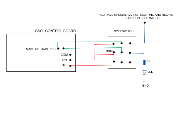
. Thanks for your help!
 
Hey guys

1. Could anyone confirm for me if this diagram is correct?

http://www.hausverwaltung-heger.de/al_leck_trick/ssl_mod.pdf

Trying to figure out a way to use a led for bypass Indication. What would i do with the COM-ON-OFF connections on the control pcb?

2. alternatively, where would i connect the Led in this layout ?
GSSL_bypass.gif
 
Imagine signal coming in to the switch (COM  -  "common" PIN - the one in the middle of the switch) , from which you can send it to two different directions. You doing this by pressing switch up or down. First Direction is "ON" second direction is "OFF".  When You press switch up signal from "com" (middle pin) goes to the "on" that means that compression is ON.  When you press switch down, signal from "com" goes to "Off" pin and that means compression is "off".

So Now let's add some more features to that because we have DPDT switch it means like to switches in one.
Lets say when you switch is in "ON" possition, your "Make up Gain" Pins connects.  When your switch is in "Off" possiton, this connection brokes.

So your switch which is basicaly 2 switches in one, have another one common pin. To that pin you plug one connection from control pcb and the other connection from control pcb you plug in to the switch "ON" pin.  So When it's "On" posstion this connection will be but when you press switch to off possition this connection will brake.

Now, one switch controls to thing turn on and off the compression and it turn on or off "Make Up gain" connection. Exactly what you want.

Try to draw it on the paper and it's all comes clear.

So yeah it's right diagram only i think you need blue cable only to off position on bypass, no need to solder to pins on switch together.
 
Olegarich said:
Imagine signal coming in to the switch (COM  -  "common" PIN - the one in the middle of the switch) , from which you can send it to two different directions. You doing this by pressing switch up or down. First Direction is "ON" second direction is "OFF".  When You press switch up signal from "com" (middle pin) goes to the "on" that means that compression is ON.  When you press switch down, signal from "com" goes to "Off" pin and that means compression is "off".

So Now let's add some more features to that because we have DPDT switch it means like to switches in one.
Lets say when you switch is in "ON" possition, your "Make up Gain" Pins connects.  When your switch is in "Off" possiton, this connection brokes.

So your switch which is basicaly 2 switches in one, have another one common pin. To that pin you plug one connection from control pcb and the other connection from control pcb you plug in to the switch "ON" pin.  So When it's "On" posstion this connection will be but when you press switch to off possition this connection will brake.

Now, one switch controls to thing turn on and off the compression and it turn on or off "Make Up gain" connection. Exactly what you want.

Try to draw it on the paper and it's all comes clear.

So yeah it's right diagram only i think you need blue cable only to off position on bypass, no need to solder to pins on switch together.

thanks for your explanation, although it was not exactly what i asked. where would i connect the bypass LED in this layout?
 
Led on control board i believe is power indicator, it's not a bypass led. So either you press compression on or off led will be working. If you would like a led to turn on with compression on, you need 3p2t switch, it's like 3 switches in one. 3 used for a led. You take power from power supply,  to the switch and from there to the led with drop resistor.
 
Olegarich said:
Led on control board i believe is power indicator, it's not a bypass led. So either you press compression on or off led will be working. If you would like a led to turn on with compression on, you need 3p2t switch, it's like 3 switches in one. 3 used for a led. You take power from power supply,  to the switch and from there to the led with drop resistor.

thanks for your message. but isn't this exactly what he did here?
http://www.hausverwaltung-heger.de/al_leck_trick/ssl_mod.pdf  :eek:

EDIT: i just found out that this is not what i am looking for (had been discussed earlier: https://groupdiy.com/index.php?topic=34219.40). It turns off the LED when in Bypass but the meter is still moving and showing compression. So a 3PDT switch is probably what i am looking for??
 
weiss said:
thanks for your message. but isn't this exactly what he did here?
http://www.hausverwaltung-heger.de/al_leck_trick/ssl_mod.pdf  :eek:

EDIT: i just found out that this is not what i am looking for (had been discussed earlier: https://groupdiy.com/index.php?topic=34219.40). It turns off the LED when in Bypass but the meter is still moving and showing compression. So a 3PDT switch is probably what i am looking for??

To add an LED directly to the 3PDT switch (on-on), put the power in the center of the 3rd pole, and the led on the position you want it to be one.

Think of it as an LED on/off switch, travelling next to the bypass switch on a 3rd rail.

Gustav
 
Gustav said:
To add an LED directly to the 3PDT switch (on-on), put the power in the center of the 3rd pole, and the led on the position you want it to be one.

Think of it as an LED on/off switch, travelling next to the bypass switch on a 3rd rail.

Gustav

i get it now! thanks gustav  :) :)
 
okay i got it up and running. sound is bypassing but there is a loud hum starting at 100Hz (and then 200Hz, 300Hz etc.). As as soon as i disable the bypass it completely distortes and the hum increases. It doesn't sound like the typical mains hum but more like a faulty component. Any clues??  ???


Another problem is, that the potentiometers don't work, unit doesn't seem to compress. I am using the Rev #7 with onboard power transformer. I included the SC HPF between the 20uf cap and the 20k resistor but a solder point got loose so i had to make a trace on top of the board. but the actual connection is there so that can't be the reason.

Pics from the unit:
 
Well it's hard to say from that pictures.
A little thing about "bypass switch". In this compressor it calls "compression" when you press it "on" and your led turn ON, it actually in compression mode, when you press it down and led is not shining, then it's in bypass mode, no compression hapening. If you wired by diagram i gave you.

1. Sidechain Filter in schematic is inserted between 33K and 22uf, but probabyl that not a problem.

2. Which potentiometer not working? Threshold? How about make gain? Doest it works?

3. You hear that big hum no matter it's in compression mode or bypassed?

First i would check if you are getting all the right voltages in IC's. In the same time check do is there no V where they shouldn't be.


Sorry typed in phone.

1. Check 15V , -15V, 12V and -12V voltage in IC's, where they should be
2. Check are those voltages in IC's where they should not be.

First I always check PSU voltages. Are those right and is there no DC where it should not be.
 
Just finished my ultimate gssl. With turbo, sidechain, hardbypass and most importand crush&blend mod. If you want to use it on master bus i think those mods gives you much more space to trim this unit to your needs. Sounds freaky good! Thanx gyraf and all others
 

Attachments

  • 0B87A471-9D37-4735-95E9-E6A932D5F692.jpeg
    0B87A471-9D37-4735-95E9-E6A932D5F692.jpeg
    1.2 MB · Views: 24

Latest posts

Back
Top