My first tube project help thread (NYD one bottle)

GroupDIY Audio Forum

Help Support GroupDIY Audio Forum:

This site may earn a commission from merchant affiliate links, including eBay, Amazon, and others.
When you are measuring the noise with RMAA do you have the input connected to your soundcard? You don't want to leave the input unconnected. I ask because you aren't showing any level from the RMAA test signal, only the noise. Preamps can hum from having an open input.
Either hook up the input to your soundcard or use a source resistor on the input (like 150 ohm between pins 2&3).

I had high noise in my BA2 until I added 100 ohm resistors to ground from the heaters. Earlier you said you were putting in 80 ohm resistors. Was the noise still high after that?

The way I measure preamps with RMAA (noise, freq response, etc), is hook up the soundcard and reduce the level into the preamp ~40 dB (whatever amount of gain the preamp adds). Then the RMAA screen will show the return level as correct. Then hit 'start test'. In the results you will see a 'noise' test and you can view a plot (like what I show here: http://www.groupdiy.com/index.php?topic=49123.msg622338#msg622338)
 
Adam Smith said:
Are those Sowter input transformers? Looking at your pic, it occurred to me that your problem is actually probably that input iron. Get that outta there and mail it to me for analysis immediately. It will take me several years, but I will most likely be able to tell you if it's useable or not.

haha you have a good sense of humor.
 
dmp said:
When you are measuring the noise with RMAA do you have the input connected to your soundcard? You don't want to leave the input unconnected. I ask because you aren't showing any level from the RMAA test signal, only the noise. Preamps can hum from having an open input.
Either hook up the input to your soundcard or use a source resistor on the input (like 150 ohm between pins 2&3).

I had high noise in my BA2 until I added 100 ohm resistors to ground from the heaters. Earlier you said you were putting in 80 ohm resistors. Was the noise still high after that?

The way I measure preamps with RMAA (noise, freq response, etc), is hook up the soundcard and reduce the level into the preamp ~40 dB (whatever amount of gain the preamp adds). Then the RMAA screen will show the return level as correct. Then hit 'start test'. In the results you will see a 'noise' test and you can view a plot (like what I show here: http://www.groupdiy.com/index.php?topic=49123.msg622338#msg622338)

I have not been using the sound card output into the mic preamp input. I have had both pads engaged with the unit at full gain with a 58 in each preamp channel. the mics are in a very quiet room. 

I'm switching to a bunch of shielded wire that I have laying around from a patch bay that I did a few weeks ago. I'm going to stick to the basics. All leads as short as possible and shielded cable. Ill move the xfrmrs as far away as possible and see what this does.

 
well, before I started putting my build back into a chassis, IT DROPPED MY NOISE FLOOR BY 15dB. I went from -65 "ish" to around -80 "ish."

Hopefully going back into the chassis does not send me backwards with the noise reduction.
 
I definitely stuffed the chassis better this time!

But my hum came back :(

The clean channel was the best sounding pre-amp that I have had in my studio thus far :)

I'm relocating the transformers today to see what happens. I'm going to see if I can stuff the in and out iron of the channel that is closer to the power transformer inside of the chassis.

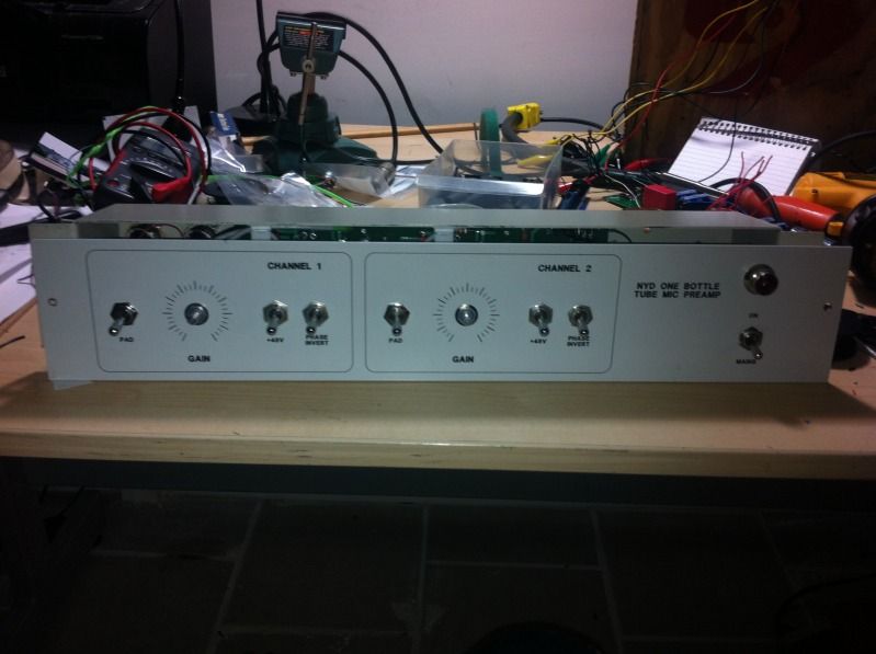
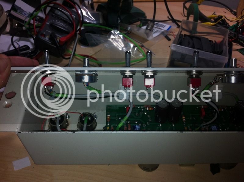
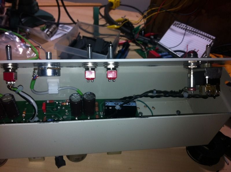
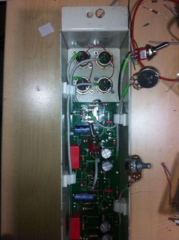
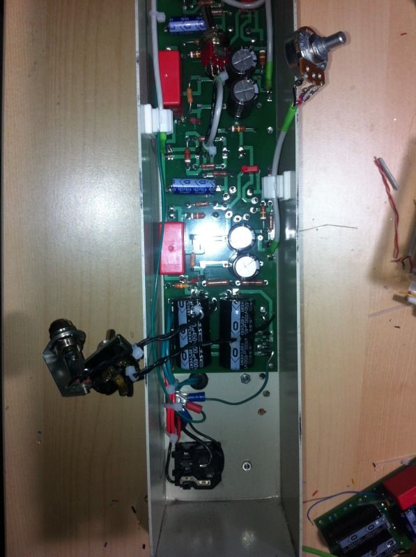
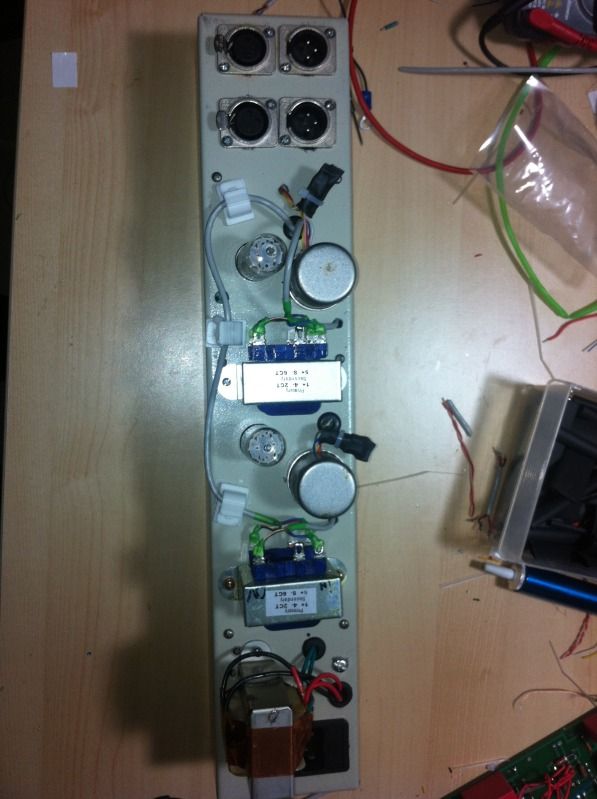
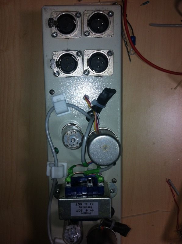
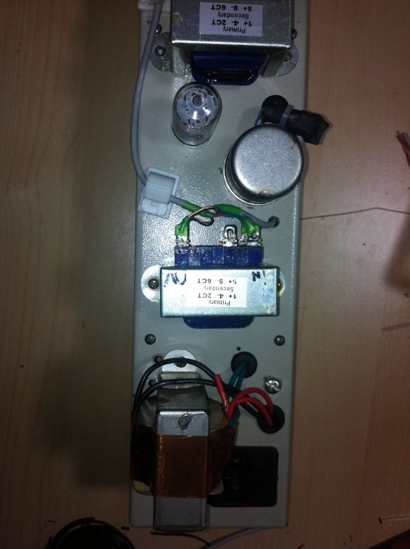
How does it look to you guys?

IMG_1004.jpg

IMG_1005.jpg

IMG_1006.jpg

IMG_1007.jpg

IMG_1008.jpg

IMG_1009.jpg

IMG_1010.jpg

IMG_1011.jpg
 
The input & OT of the one channel look too close for comfort to the PT.

What's the best hum reduction you get from rotating the input transformer? (as it is shown mounted on the outside)


I'm going to see if I can stuff the in and out iron of the channel that is closer to the power transformer inside of the chassis.


May be your best bet - assuming that all the hum is coming from PT proximity.  It sounds like at least some is.  Rotating the input will give an idea of how much.


Another factor may be the steel chassis - looks like you're using a Hammond 525.  It's one of those things that is warned about - steel being a conductor for magnetic fields.  Since your other channel performs well it may only be a proximity issue.
 
lassoharp said:
May be your best bet - assuming that all the hum is coming from PT proximity.  It sounds like at least some is.  Rotating the input will give an idea of how much.

Or maybe the opposite? Mount the power transformer inside?
 
dustbro said:
lassoharp said:
May be your best bet - assuming that all the hum is coming from PT proximity.  It sounds like at least some is.  Rotating the input will give an idea of how much.

Or maybe the opposite? Mount the power transformer inside?


Yeah, I thought about that.  Not sure if it would get into the input sec wires or sensitive PCB traces but worth a shot if all else fails.
 
got bored, built one p2p

No signal passes post the zobel network, I def see some signal at my input xlr pins but nothing post input transformer. When the transformer is disconnected from the circuit I do get signal but once I connect the transformer back up to the zobel network/grid of v1, and ground (as according to the schematic) the signal seems to die off. hahahaha I have probably rebuilt this thing 5 times in 5 different ways! I'm not giving up.

but all else seems to be decent. not perfect, but decent.

Here are my voltages on the 12AV7

Pin 1: 72vdc
Pin 2: (grid of triode #1) 0v :( ? (this is with 0.775vac 1Khz sine wave applied at full gain from the pot with the output going into another unit for closer to perfect loading while testing. the other unit is turned off.)
Pin 3: 1.49vdc
Between pins 4 and 5: 6.8vac (AC heaters)
Pin 6: 129.7vdc
Pin 7: 0.009vdc
Pin 8: 1.4vdc
pin 9: not connected (heater center tap)
Power supply after R13: 222vdc

D1CA2A4C-227B-4F90-868F-0F92EE60DBDD-685-00000115C85CCEC6.jpg

8CB6F91D-F72E-4CFB-A4C7-BA9B92E1B169-685-00000115B910B372.jpg

4A2A06BF-CFAC-4AC0-B658-00149BCD36C6-685-00000115A65034E6.jpg


I aint pretty but it's close to working and it's the second thing I've ever made p2p.

EDIT* found my mistake; missing trace and the circuit will not function without the input pad.. I don't really understand why the pad HAS to be there but it does...
 
buildafriend said:
No signal passes post the zobel network, I def see some signal at my input xlr pins but nothing post input transformer. When the transformer is disconnected from the circuit I do get signal but once I connect the transformer back up to the zobel network/grid of v1, and ground (as according to the schematic) the signal seems to die off.

Sounds like your signal path is hitting ground. disconnect your input transformer and check for continuity between ground and Pin 2 of the tube.
 
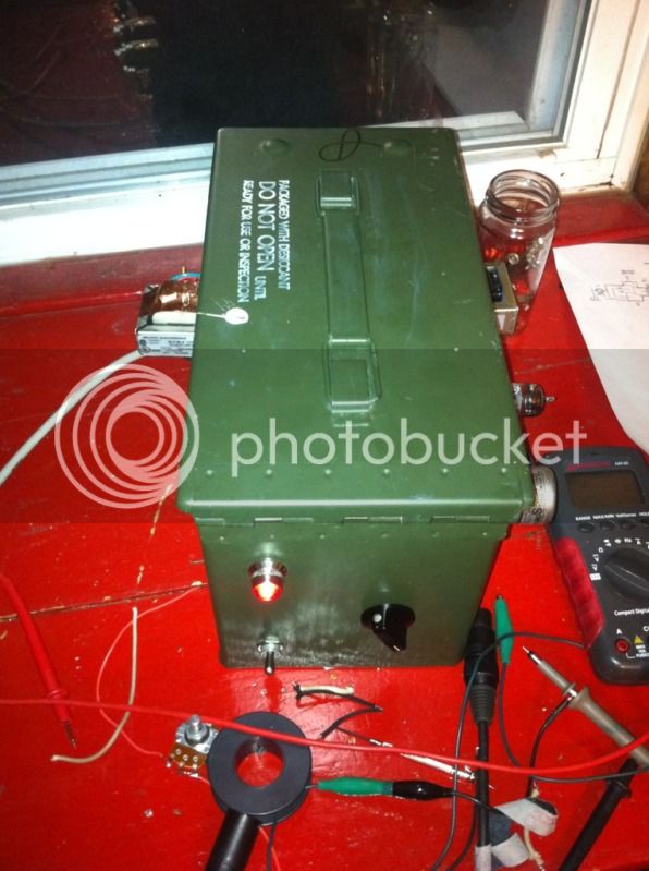
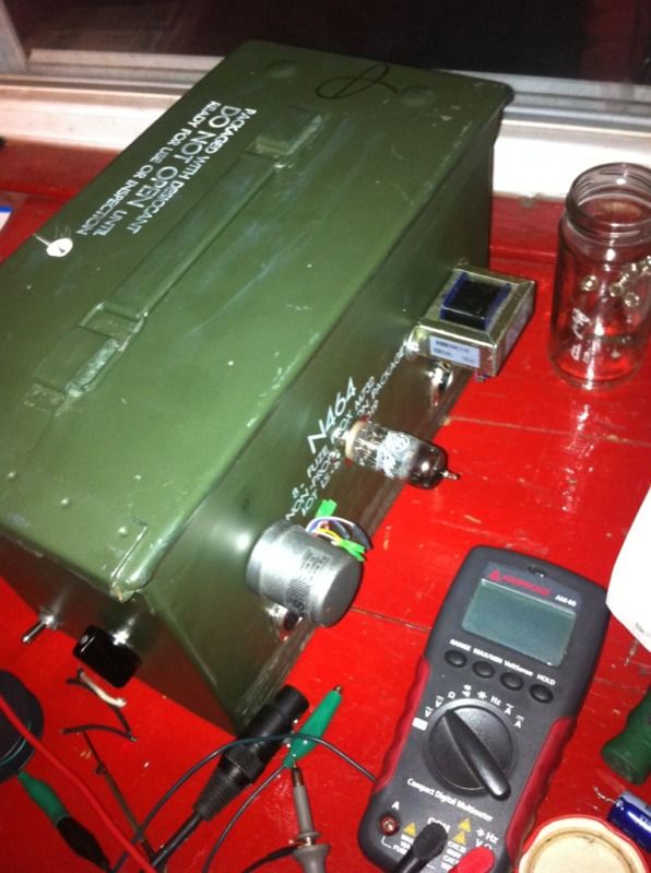
got my military ammo box one bottle up and running. It's a great portable piece and it sounds amazing. all it needs is a little phantom power

I appreciate everyone's help
 
I tried running it without the pad resistors, it only works with them in. weird right? I dont know why it wont work without them but I would sure love to learn why.  :)
 
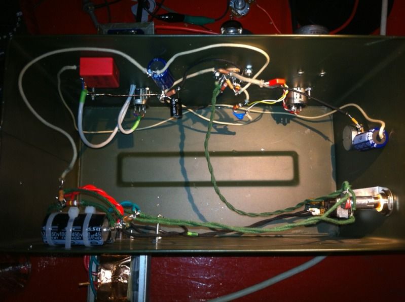
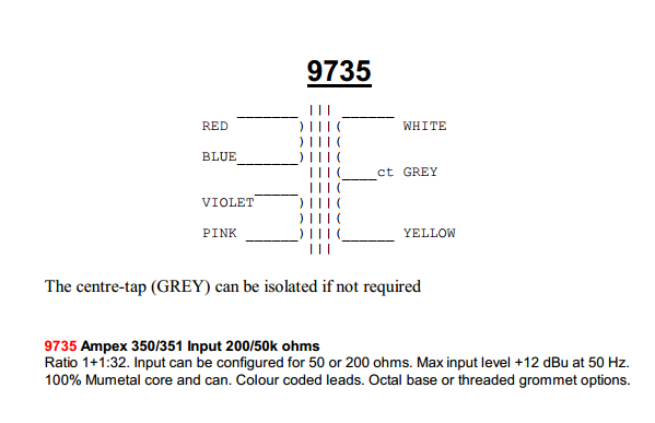
The red wire is hitting pin 2 of the input xlr which is twisted to a pink wire that hits pin 3. It's possible that they look soldered together since they are sort of close in color.

ampex350.png
 

Latest posts

Back
Top