You are using an out of date browser. It may not display this or other websites correctly.
You should upgrade or use an alternative browser.
You should upgrade or use an alternative browser.
Alctron BV300 (T.Bone Retro Tube II) to half of AKG C24 mod
- Thread starter telefunk
- Start date


Help Support GroupDIY Audio Forum:
This site may earn a commission from merchant affiliate
links, including eBay, Amazon, and others.
Ok, now my
-B+ is 121,6v
-heater 6,2v
-Pattern voltages are:0v-51,6v-105,8v (but i'm aiming at 0v-60v-120v) coming from the PSU.
The question is, as i'm trying to clone the AKG C24, should i change all those 51M and 1G reasistors to 200M too, as in the C24 schematic?
All help would be greatly appriciated!
-B+ is 121,6v
-heater 6,2v
-Pattern voltages are:0v-51,6v-105,8v (but i'm aiming at 0v-60v-120v) coming from the PSU.
The question is, as i'm trying to clone the AKG C24, should i change all those 51M and 1G reasistors to 200M too, as in the C24 schematic?
All help would be greatly appriciated!
telefunk said:Ideas to improve the PSU design? Anybody?
You could get rid of the zeners and the (possible) switching noise, and use bigger value R5 to achieve the right B+. That may lead to capacitor popping voltage unloaded though.
Changing the 1G grid to ground to 200M -> less (sub)bass.
Measurements done with a load?
You could get rid of the zeners and the (possible) switching noise, and use bigger value R5 to achieve the right B+. That may lead to capacitor popping voltage unloaded though.
Changing the 1G grid to ground to 200M -> less (sub)bass.
Measurements done with a load?
Yes, all measurements done loaded. (pun intended)
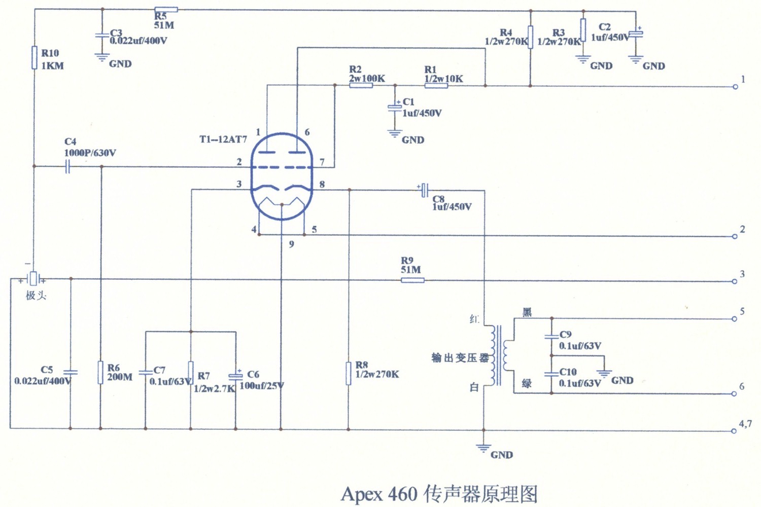
Actually the grid to ground is 200M originally here, as it is in Apex 460 too.
But the question i'm wondering is, if using the CK12 capsule and T14/1 transformer, original B+ and pattern voltages, should i also use all original resistor values?
That would make sense?!
Anyway, tuhannet kiitokset!
If you're aiming for a clone you should use the original values for all the resistors and capacitors but then you should also use an original brass ring CK12, correct head basket, body etc... I would just try to build a good mic and use the resistors that are already there or experiment with different values, maybe try a smaller grid to ground value.
Good read: http://www.groupdiy.com/index.php?topic=28519.0
BTW, I'm not sure if it fits the capsule mount in your mic but I highly recommend Tim Campbell's CT12.
Good read: http://www.groupdiy.com/index.php?topic=28519.0
BTW, I'm not sure if it fits the capsule mount in your mic but I highly recommend Tim Campbell's CT12.
pasarski said:BTW, I'm not sure if it fits the capsule mount in your mic but I highly recommend Tim Campbell's CT12.
I believe it's going to fit, one way or another. I'm waiting for Tim's CT12 already!
Thanks,
if it doesn't fit with the original 4 point silicone strap thing, i'm going to do some metal work with the lollipop head assembly and then it fits with Tim's own mount for sure.
Good thing is, that Alctron BV300 35mm capsule has exactly the same dimensions as CT12.
Thanks for the link, btw, it was a good read!
Together with AMI T14 it should rock. The head assembly is the only question mark...
Pidetään sormet ristissä, as we say.
telefunk said:-Pattern voltages are:0v-51,6v-105,8v (but i'm aiming at 0v-60v-120v) coming from the PSU.
shouldn't really make a big difference... maybe a little less volume, but imho should be fine. could be fixed though, but I wouldn't worry about it.
evil grill
Well-known member

What's the diode for?evil grill said:Howdy!
Since Retro Tube II is really cheap now I have bought 2 that I will try to improve.
I would apprechiate help identifying problems with my plan.
See attached schematic.
evil grill
Well-known member
abbey road d enfer said:What's the diode for?
Saving the life of the tube at start-up.
www.valvewizard.co.uk/dccf.html
evil grill
Well-known member
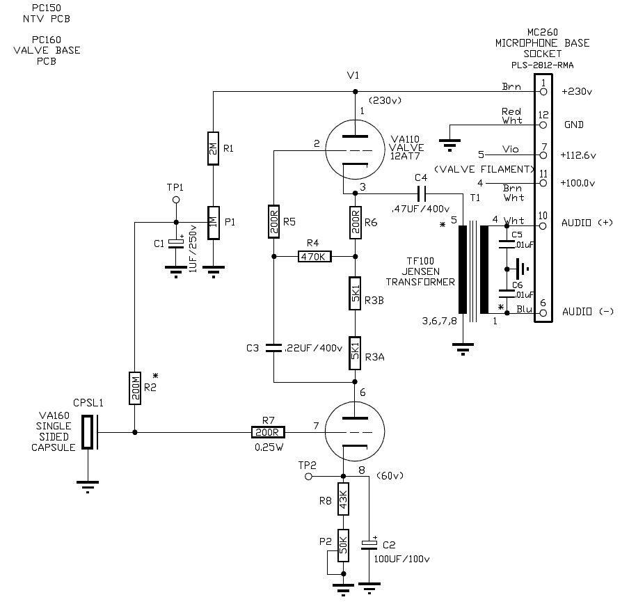
The values for resistors connected to the capsule are copied from http://www.tab-funkenwerk.com/sitebuildercontent/sitebuilderpictures/C12-Alternative-for-AMI-PSU.jpg

I was thinking of copying that schematic but I don't know if rebuilding the heater supply is worth the trouble + I would like to keep the cathode follower and I do not know how to design it if I change the first triode.
I was thinking of copying that schematic but I don't know if rebuilding the heater supply is worth the trouble + I would like to keep the cathode follower and I do not know how to design it if I change the first triode.
> Saving the life of the tube at start-up.
Not with 51k in series. 98% of stray current flows in grid, 2% in diode. Stray current is a mA at most which won't hurt the grid.
What is in fact wrong with the mike as-is? If you just want a change to have a change, paint it purple. Color can have a large effect on sonic perception. (I wish I still had my brass microphone but it needed constant buffing.)
evil grill
Well-known member
PRR said:> Saving the life of the tube at start-up.
Not with 51k in series. 98% of stray current flows in grid, 2% in diode. Stray current is a mA at most which won't hurt the grid.
What is in fact wrong with the mike as-is? If you just want a change to have a change, paint it purple. Color can have a large effect on sonic perception. (I wish I still had my brass microphone but it needed constant buffing.)
Purple would contrast nicely against my green room, but I won't paint it purple. Might do dark green.
The mike is actually really good for the money. I would like to hear a microphone that can sound nice after EQ and compression. Also I would like to solder some audio stuff. I have'nt had the time or lust to do DIY for over ten years and all of a sudden I wan't to turn something electric into something better. I have no experience with microphones. Apart from repair and maintainance I've built fuzz-boxes and simple guitar amps and upgraded components in audio gear. Right now I have inspiration to learn.
evil grill
Well-known member
VAC not measured but taken from marking on transformer.
Edit: Microphone connected during measurement.
Edit 2: Got suspicious. Measured with calibrated meter at work. B+ is 150 V without load. My voItmeter is broken.

I removed the image.
LevinGuitar
Well-known member
- Joined
- Jun 13, 2019
- Messages
- 406
I'm modding my Retro Tube and wonder what R11 is for, the apex 460 don't have it and the Rode NTV have a 0.22uf cap + 200R resistor there. Is it filtering something?
And why C11 is there and not after cathode? Is there no difference where to place the HF roll of?
Thanks!
And why C11 is there and not after cathode? Is there no difference where to place the HF roll of?
Thanks!
Last edited:
Where is R11 in the schemo? Do you have a better schemo than this one, which has several mistakes.I'm modding my Retro Tube and wonder what R11 is for,
Please post a schemo when you ask such a question. We don't have all the schematics in teh world.the apex 460 don't have it and the Rode NTV have a 0.22uf cap + 200R resistor there. Is it filtering something?
Where is C11?And why C11 is there and not after cathode? Is there no difference where to place the HF roll of?
LevinGuitar
Well-known member
- Joined
- Jun 13, 2019
- Messages
- 406
Sorry, here it goes:
R11 is between the plate of first stage and grid of the second stage. C11 from R11 to ground. I have increased the value of C11 to 390pf (from cathode of the second stage to ground), and now have better response for speech. Is there something I'm missing because of moving it?

Here is the similar Apex 460 (no R11)
And the NTV
R11 is between the plate of first stage and grid of the second stage. C11 from R11 to ground. I have increased the value of C11 to 390pf (from cathode of the second stage to ground), and now have better response for speech. Is there something I'm missing because of moving it?
Here is the similar Apex 460 (no R11)
And the NTV
Attachments

Last edited:
C11 acts in conjunction with R11 and the internal impedance of teh tube to produce a roll-off starting at about 10-12kHz. I'm not sure it has much perceptible effect, but it it sounds good to you, it's OK.R11 is between the plate of first stage and grid of the second stage. C11 from R11 to ground. I have increased the value of C11 to 390pf (from cathode of the second stage to ground), and now have better response for speech.
Moving it from where?Is there something I'm missing because of moving it?
Yes, many mfgrs keep the sibilant response because customers are attracted to it when the test the mic. Only to find out later that they would like it less sibilant.Here is the similar Apex 460 (no R11)
This one is very different in many respects. You just can't compare.And the NTV
Last edited: