PSU wiring Help

GroupDIY Audio Forum

Help Support GroupDIY Audio Forum:

This site may earn a commission from merchant affiliate links, including eBay, Amazon, and others.

SaMpLeGoD

Well-known member
Joined
Jul 19, 2007
Messages
441
Location
Portugal
Hi all,

I'm building a device that I'll need +24v, +48v, +15v, +12v and  -15v, and I have here the Igor's 2448 PSU and some Keith's SSL9k PSU hanging around... so I'm trying with the thing I have here ;)
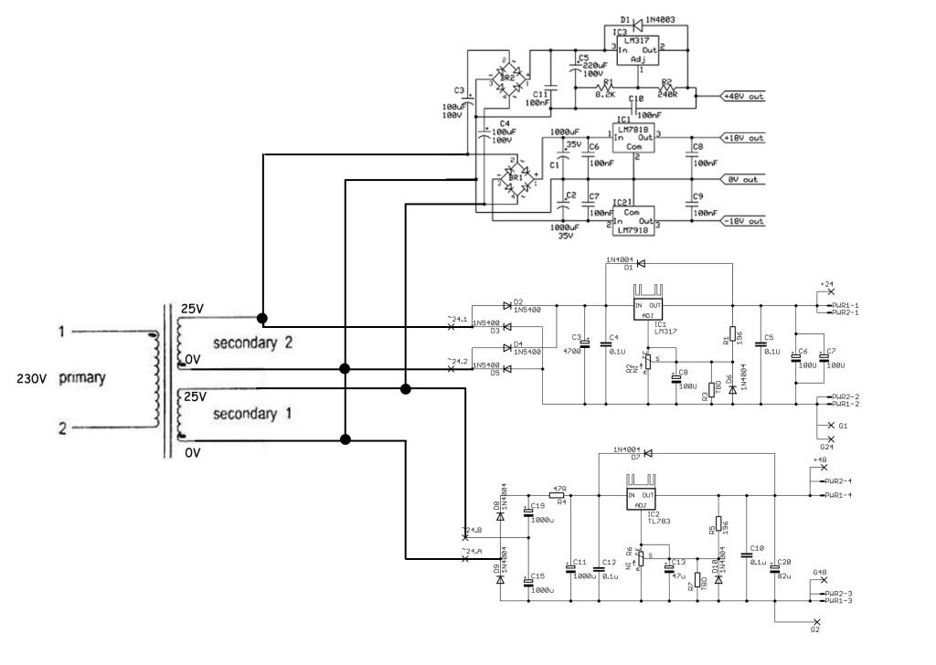
Will I get in trouble if I connect the things like in the pic below?
Thanks for the help ;)

PSUSchematicHelp.jpg
 
SaMpLeGoD said:
I'm building a device that I'll need +24v, +48v, +15v, +12v and  -15v, and I have here the Igor's 2448 PSU and some Keith's SSL9k PSU hanging around... so I'm trying with the thing I have here
Will I get in trouble if I connect the things like in the pic below?
Might smell funny ...
What's the current load per rail ?
I'd probably start by fixing the transformers center tap connection and continue with the followups.
Your 25VAC rails will get rectified to raw DC voltages that exceed the max.rating of your 78xx/79xx regulators.
Didn't you also want a +12V rail ? Your drawing shows two +48V rails at the voltage doublers.
 
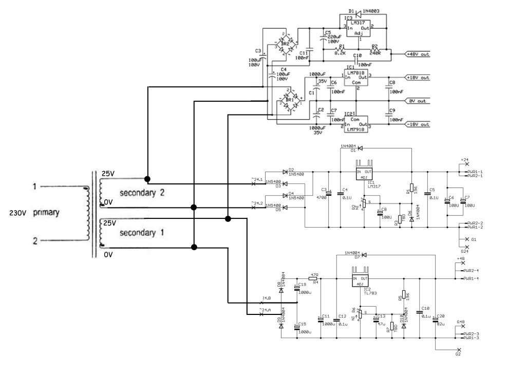
Maybe this way?

PSUSchematicHelp2.jpg


I'm planning to use the Igor's 2448 48v rail for phantom power, and use the keiths one to generate +15 / -15 just swapping the 7818 / 7918 by 7815 / 7915, and using the 48v rail as 12v, since it's using LM317 and I removed the fixed resistor an put a trimmer instead... so I can down the voltage to 12v in that rail.
Am I thinking right? the module I'm making doesn't draw too much current... below 1A from the toroidal that is 50VA (25 - 0 / 25 - 0)
Thanks!
 
SaMpLeGoD said:
Maybe this way?
Anything changed? Same (out of phase) center tap connection.

I'm planning to use the Igor's 2448 48v rail for phantom power, and use the keiths one to generate +15 / -15 just swapping the 7818 / 7918 by 7815 / 7915
25VAC * 1.414 - rectifier diode drop will exceed the max.input voltage of these fixed 78xx/79xx regulators that -in case they survive- will transfer the voltage difference to heat until they go into thermal shutdown.

and using the 48v rail as 12v, since it's using LM317 and I removed the fixed resistor an put a trimmer instead... so I can down the voltage to 12v in that rail.
The voltage doubler in front will make generated heat even worse. The voltage difference between input/output exceeds the LM317 abs.max.ratings as well.
 
Well...  do I need a second power transformer??
I thought I was able to use it in that way, but you right harpo :(
Could any different wiring solve my problem?
Thanks a lot!
 
jepp, except PRRs +/-25V raw DC might look more than above +/-35VDC with your dual 25VAC secondary transformer in front and this exceeds the 35V abs.max. input voltage rating of the fixed regulators. A series resistor in front of each voltage regulator seems the easiest way do drop this into a safer and heat sharing region if you are married with your 2*25V transformer. Ohms law will help to get their needed value and rating. Keep in mind, the 230VAC mains isn't a constant and can vary between 207-253VAC within europe.
 
Thanks for the replies Harpo e PRR!

What about this solution?

PSUSchematicHelp3.jpg


Just a quick question... can I connect the 2 x 0V of the toroidal togheter?
I need a 3 connection to other part of the device that needs 25 - 0 - 25
Thanks a lot
 
Noone could prevent you from connecting them out-of-phase, but this wouldn't be the needed center tap. You want both windings connected in series with an in-phase end and an out-of-phase end at the outer combined windings ends. Have a look at PRRs drawing again (especially the dots at the windings ends and how the windings combine).
 
> PRRs +/-25V raw DC might look more than above +/-35VDC with your dual 25VAC

Good catch. Thanks.

> A series resistor in front of each voltage regulator seems the easiest way do drop this

No; because current is uncertain and can probably drop to zero, which is zero voltage drop, and full 37V into 35V max chips.

 
Well, ok. I think is better get another toroidal to supply the +15V / +12V / -15V with less input voltage like 18 - 0 - 18 on the secondary.
But can I connect the 2x 0V of the toroidal secondary without arm the +24 / +48 Igor's PSU?
I need to supply 25 - 0 - 25 to another part of the circuit :(
Thanks!
 
> No; because current is uncertain and can probably drop to zero, which is zero voltage drop, and full 37V into 35V max chips.
Good catch as well, hence my 1st.question to SaMpLeGoD for the current draw per rail, but you're probably right, so thanks in return.
 
SaMpLeGoD said:
Well, ok. I think is better get another toroidal to supply the +15V / +12V / -15V with less input voltage like 18 - 0 - 18 on the secondary.
looks like the better plan.
Depending on current draw of your rail voltages you might connect the +/-15V and +12V regulator inputs after your +24VDC (and -24VDC) rails, but these 24V regs then have to stand the total current draw of all connected rails and probably would need serious heatsinking.

But can I connect the 2x 0V of the toroidal secondary without arm the +24 / +48 Igor's PSU?
I need to supply 25 - 0 - 25 to another part of the circuit :(
Get rid of the idea, each transformer winding comes with a 0V wire end.
A transformer transforms an applied AC voltage in to an AC voltage out at a specific ratio. The dots at the transformers schematic symbol indicate, which wire is the in-phase/hot end of a primary and secondary windings end in respect to its other side for the same snapshot moment. This 0V or 25VRMS at your transformer drawing is only another way of indicating where the in- or out-of-phase winding end is located (and is missing the corresponding 0V (1) or 230VRMS (2) at primary side). Its a point of reference for measuring the floating voltage across this winding for the moment when the amplitude of AC mains is at maxRMS in respect to the other windings end. This will be different or just the other way round again, depending on the snapshot moment of your local 50 or 60Hz AC cycle. When both of your secondary windings (2*25V) have the same primary:secondary ratio (230V:25V+25V or 1:0.1087+0.1087 turns ratio) and you connect these secondary windings in series in their correct orientation, this will make these combined windings behave as a single secondary winding (230V:50V or 1:0.2174 turns ratio) with a single in-phase/hot end at one side, an out-of-phase/cold end at the opposite combined winding side and a center tap in the middle of both combined windings.

For your Igors only +24V, not -24V and +48V PSUs and */keeping the transformers center tap connection for your 0V reference voltage/*, leave out D3 and replace D5 with a wire link. D6 will better be across R1 (not across the paralleled R3, C8 and rheostat R6) to protect your LM317 regulator from C8 discharging. Same goes for D10 better being across R5, if C13 is needed at all (TL783 datasheet, other than LM317/337, implies to better leave this part out).

*/edit: Igors 2448 PSU is designed for two separate secondary windings (no center tap) and without a common reference voltage, so keeping both separate you will have to fit D3 and D5 as drawn.
 
just popping in to ask,since I might be under false understanding...

isn't the 35V rating for i/o difference, and not just total input dc? I've used 317 for 48v a couple times with no fire...
 
gemini86 said:
just popping in to ask,since I might be under false understanding...

isn't the 35V rating for i/o difference, and not just total input dc? I've used 317 for 48v a couple times with no fire...
True for the LM317/337. The answer was related to the 78xx/79xx where the abs.max. input voltage (not i/o differential) must not exceed 35V for the up to 15V regulators or 40V for the 18V, 20V or 24V regulators.
The catch with the abs.max.40V i/o differential for the LM317 is when -for the more common failure- a balanced mic cable gets shorted to phantom reference voltage and the often underrated 6K81 phantom feeding resistors fail short or open. As these don't fail simultaneously, pic your poison whether a blown phantom voltage rail or a blown mic input stage without clamps, that for a moment sees a 48V differential instead of common mode, now is the bigger evil. After you replaced the broken mic cable, the LM317 when failed short now feeds the raw pre regulator DC voltage to your mic that might not like this. Same max.i/o exceeding failure mode could be caused at startup as well, depending on capacitance of uncharged caps behind your regulator. A zener clamp across the regulators i/o in parallel to the protection diode should catch this for a short period of time. A LM317-HV type (max.i/o 60V) would have a better chance to survive. A TL783 (max.i/o 125V) still seems the safer bet. YMMV.
 
I will just solve my problem in a different way.
I found a Mnat's PSU hanging around, so I will forget Igor's PSU, and will use the SSL9K PSU to generate the Phantom (+48V) and the +24V rail. Since using LM7824 to do that, I'll have no problem with the voltage in excess with the toroidal, right?

The Mnats PSU have an adjustable positive and negative rails with LM317 and LM337... so I think I can use that to my +15V and -15V rails... since i/o maximum voltage for these regulators is more than 40v I think.
The +12V rail... I drop from the +15V rail... that's it...
What do you guys think about that?

Thanks
 
Thanks for the in depth answer. :) this place still rocks! 
Harpo said:
gemini86 said:
just popping in to ask,since I might be under false understanding...

isn't the 35V rating for i/o difference, and not just total input dc? I've used 317 for 48v a couple times with no fire...
True for the LM317/337. The answer was related to the 78xx/79xx where the abs.max. input voltage (not i/o differential) must not exceed 35V for the up to 15V regulators or 40V for the 18V, 20V or 24V regulators.
The catch with the abs.max.40V i/o differential for the LM317 is when -for the more common failure- a balanced mic cable gets shorted to phantom reference voltage and the often underrated 6K81 phantom feeding resistors fail short or open. As these don't fail simultaneously, pic your poison whether a blown phantom voltage rail or a blown mic input stage without clamps, that for a moment sees a 48V differential instead of common mode, now is the bigger evil. After you replaced the broken mic cable, the LM317 when failed short now feeds the raw pre regulator DC voltage to your mic that might not like this. Same max.i/o exceeding failure mode could be caused at startup as well, depending on capacitance of uncharged caps behind your regulator. A zener clamp across the regulators i/o in parallel to the protection diode should catch this for a short period of time. A LM317-HV type (max.i/o 60V) would have a better chance to survive. A TL783 (max.i/o 125V) still seems the safer bet. YMMV.
 

Latest posts

Back
Top