output transformer low-end bump?

GroupDIY Audio Forum

Help Support GroupDIY Audio Forum:

This site may earn a commission from merchant affiliate links, including eBay, Amazon, and others.

plumsolly

Well-known member
Joined
Nov 3, 2007
Messages
969
Location
Denver, Colorado
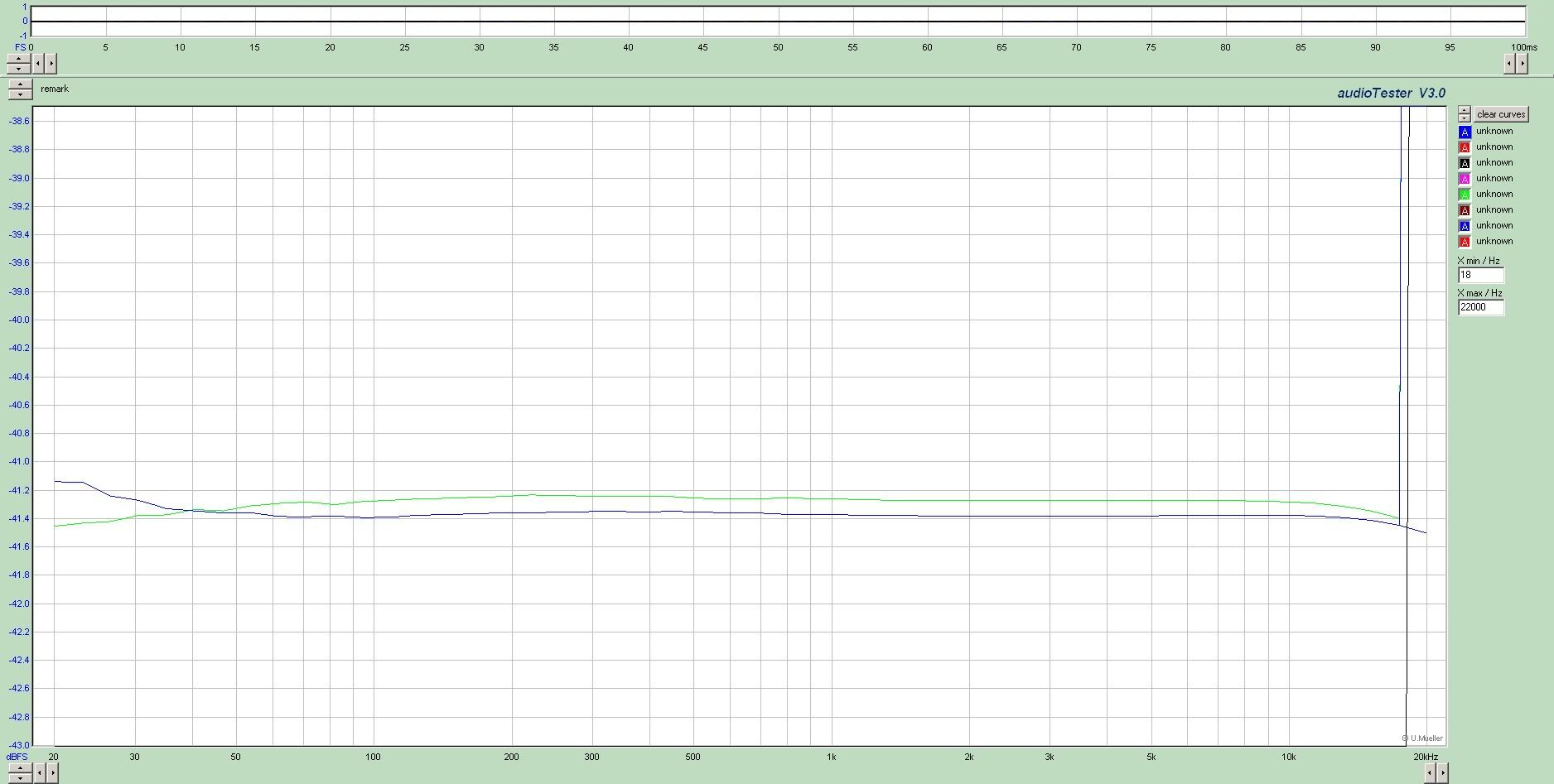
I racked up a pair of Electrodyne 710L channels recently. Initially I had EA1066s on the outputs, but I was getting a pretty hefty bump around 20hz on the output. This bump also changed somewhat with the position of the fader. I figured the Electrodynes were just having trouble driving a 200Ω:150Ω transformer. I switched in a UTC HA-108X 500Ω:500Ω and it looked much better. Since I only had one UTC, I ordered a pair of 600Ω:600Ω, but these exhibit a slightly smaller bump around the same frequency. Does anyone have any idea of whats happening here, or what else to look at? Or is this just what I get for $13/transformer? The bump is not bad, <0.5db, but I am curious about the cause. Here are some plots (notice the different Y scales):

UTC in blue and Edcor in black
electrodyne710blueisutcblackisedcor.jpg


Edcor in black, unbalanced in green
electrodyne710blueisedcorgreenisunbal-1.jpg


Thanks,

Ben
 
I expect the amps drive Z is very low, and is causing the transformers to resonate.  Try series resistance between and see if it flattens. 
 
Hi Ben,
I don't know the Electrodyne circuit myself - that would be one of EMRR Doug's area's of expertise and I haven't seen the schematic but:

That bump is really quite small and, actually I'm quite impressed with the whole spectrum for a $13 transformer  :)  To get a bit of perspective on these things, I usually zoom out for a check with the scale set to + and - 10dB of my reference level.
I assume the Edcor is a steel core and steel generally wants a low source impedance for lowest distortion - << than the DCR of the windings  (nickel is more forgiving in this regard) -  although that same distortion can also be the colour/schmutz that we want.  "Does it sound good?" is my decider in the end. 
Good luck anyway,

Cheers
 
If the transformer is fed via a cap, it will form a resonant 12dB/8ve HP filter.  The damping is determined by the source resistance (higher Rs more damping) and the load resistance (lower Rl more damping)

But the inductance (and hence damping) also varies with level.  My post at

http://www.groupdiy.com/index.php?topic=47515.40

shows this and there are extensive discussions by gurus too.
 
ricardo said:
If the transformer is fed via a cap, it will form a resonant 12dB/8ve HP filter.

If it does have a cap, and the bump bothers you, you can try a 47R or so resistor in parallel with the cap, like API uses on the 312/212 for the same reason.
 
..or use a different value capacitor, dropping resonance point to where the natural -3dBpoint of the system would be - thereby extending low-end further down...

Jakob E.
 
gyraf said:
..or use a different value capacitor, dropping resonance point to where the natural -3dBpoint of the system would be - thereby extending low-end further down...
Be careful if you do this.  A bigger capacitor will drop the resonant frequency but the bump will become bigger

A smaller load resistor on the transformer output will damp the bump but you need to make sure the circuit can drive the smaller load resistor.

It varies with fader position cos the effect is level dependent.
 
This place is amazing.

Doug, I tried some series resistance and it did pull the low end down, but at a slightly higher frequency than the bump. So by the time I tamed the bump, there was a bit of a dip above it. In the end, I couldn't find a compromise that was better than where I was at to begin with.

I also tried some loading resistors which helped a little. I settled on 800-1kΩ

I don't have a schematic for these modules, unfortunately - there just doesn't seem to be one around - I even offered to pay for one from Orphan Audio, but never heard back.

Ricardo, I image it is fed by I cap - I will trace that part of the circuit in the next couple of days. My symptoms look exactly like the plot you linked.

Looking at my notes for the recap, there are some 100uf/15v caps that are likely the ones in this position. My Auditronics and the API circuits look like they use 300-400uf caps in this position, so I wonder if raising that cap value would be the answer. 

When I have time to look at it again I will do some more experiments.

Thanks to everyone who chimed in.

Best,
Ben
 
Just an update. The transformers are indeed fed by caps, and they were indeed 100uf. I replaced them with 220uf and the response cleaned up nicely. Attached is an updated plot. Thanks to everyone for their insight.
 

Attachments

  • Electrodyne 710 edcor 220uf op cap Stereo.jpg
    Electrodyne 710 edcor 220uf op cap Stereo.jpg
    430.9 KB · Views: 66
Can you trace it down to 1Hz? As Ricardo says, changing the cap moves the bump but makes it bigger. If it is just a few dB (that part-dB "error in your first post is nothing) and you have a deliberate subsonic filter elsewhere, then it may not matter. But I'm always reminded of phono preamps with big 0.5Hz bumps going nuts on some (warped) LPs and not on others; also a speaker protection circuit which would trip-out on quite low levels of subsonics.
 
I use SpectraPlus daily on vintage gear and see a very similar thing repeatedly on certain pieces of gear. The interesting thing is if I use an oscillator and sweep the same frequency range, the bump is not there just the normal roll-off you would expect to see (the osc is not flat to 1hz, but comparing input to output, the bump is not there). In some cases a load on the secondary 'fixes' the problem I see in SpecPlus, other times it just drags the entire signal down by a dB or so.
 
plumsolly said:
Just an update. The transformers are indeed fed by caps, and they were indeed 100uf. I replaced them with 220uf and the response cleaned up nicely. Attached is an updated plot. Thanks to everyone for their insight.
Electrolytics caps do age. I bet if you had replaced the 100u caps by new 100u, they bump would have moved too.
 
q2audio said:
I use SpectraPlus daily on vintage gear and see a very similar thing repeatedly on certain pieces of gear. The interesting thing is if I use an oscillator and sweep the same frequency range, the bump is not there just the normal roll-off you would expect to see (the osc is not flat to 1hz, but comparing input to output, the bump is not there).
If the sweep is too fast, the signal rectifier in the measurement chain is not fast enough to follow the fast changes that appear when hitting the troubled frequency spot.
Sweep measurements at VLF frequencies should be done very slowly. Reducing the sweep speed improves the resolution, until it doesn't change anymore; that's when you have the best compromise between speed and accuracy.
In addition, digital measurement systems do not actually sweep; they change frequency step by step, with a resolution that is the result of a compromise between speed of measurement, complexity and accuracy. In sophisticated systems (AP) this is user-controllable, but in many cheaper systems, it is not and the sweep is too fast or there are frequencies that are impossible to trigger. If the hump is located between two adjacent spot frequencies, it won't be correctly triggered.
In some cases a load on the secondary 'fixes' the problem I see in SpecPlus, other times it just drags the entire signal down by a dB or so.
When there's a capacitor in series, loading usually works, but if the xfmr is DC-coupled to the output stage or if there's a feedback winding, loading just pads the outputs. But if the xfmr is DC-coupled, there should be no bump; it should be caused by something else.
 
q2audio said:
I use SpectraPlus daily on vintage gear and see a very similar thing repeatedly on certain pieces of gear. The interesting thing is if I use an oscillator and sweep the same frequency range, the bump is not there just the normal roll-off you would expect to see
I've just gone through http://www.spectraplus.com/Downloads/SpectraPLUS_50_UsersGuide.pdf the SpectraPlus User Guide.  It is a Spectrum Analyser and not really optimised for Frequency Response measurement.  Which mode do you use to measure Frequency Response?

Some of its modes,  eg the Noise modes, will put a very low level through the transformer at LF so the peaking is greater.  If you use an oscillator, you are probably using a high signal that reduces or eliminates the peaking.  See the link my Reply #3.
 
The way I'm using SpecPlus is with white noise as a signal source, and a hanning window comparing left/right signals. The set up is using the left output which is split, sent to the DUT and sent back to the left input. The output of the DUT feeds the right input and then a 'complex transfer function, right vs left' gives me a frequency response curve. I hope I'm describing this correctly.

The strange thing is that some units do it, others with similar output circuits don't. On any of these if I sweep it with an osc it is flat as I mentioned before. I gave up worrying about it since all I'm trying to do is make sure any given unit is working as it should.
 
Most of the systems using some kind of windowing have constant Hz resolution, that means you have the same information between 10000 and 10020 than between 20 and 40. There's nothing like a spot generator for low frequencies. Even slow sweeps generate significant error.
 
abbey road d enfer said:
Most of the systems using some kind of windowing have constant Hz resolution, that means you have the same information between 10000 and 10020 than between 20 and 40. There's nothing like a spot generator for low frequencies. Even slow sweeps generate significant error.

A measurement system that does fixed-points-per-octave is what you want.

-a
 
abbey road d enfer said:
Most of the systems using some kind of windowing have constant Hz resolution, that means you have the same information between 10000 and 10020 than between 20 and 40. There's nothing like a spot generator for low frequencies. Even slow sweeps generate significant error.
+1  Simple FFT type systems suffer from this.  Windowing introduces serious LF error too.

There are FFT systems which get around this (involving log sweeps, zillion points & downsampling) but SpectraPlus doesn't use them.

In your case, I think its a combination of dem evil digital errors and also the level dependent behaviour of transformers.

You may want to try spot frequencies using the lowest level you can get a reliable response.
 
Back
Top