Fun with Inexpensive Mics

GroupDIY Audio Forum

Help Support GroupDIY Audio Forum:

This site may earn a commission from merchant affiliate links, including eBay, Amazon, and others.

tchgtr

Well-known member
Joined
Feb 25, 2009
Messages
467
Location
Los Angeles
  I recently acquired a 2nd MXL 9000 on the used market for under $90, and wanted to share some things I do to them.
  There is another thread somewhere in the archives about this basic cardioid tube mic, which has a lot of good advice from the local gurus, but I'm too lazy to dig it up. If people are interested, jsut search "MXL 9000". I'll put the schematic up here.
It's an odd circuit, with the typically odd choices by whoever designed it regarding the output caps - a 33uf electro in parallel with a .1uf film cap - so I replace those with a single 1.85 uf film cap, and remove all the RF filtering junk just prior to the output transformer.
  It also calls for a 12AT7 in the schemo, but often comes with a 12AX7 installed. I now have some 12AV7s in both of mine, which keeps them nice and clean-sounding, but I may try some AT7s soon.
  After all this, they sound better with the original capsules, but (as the smart people around here constantly remind us), the capsule is largely responsible for the sound of a mic, and I just can't get around these Chinese U67-style capsules.
  I am using the original output tranny, and have not measured the stock tranny, nor does the schemo have any info about it. I think driving them with 12AX7 probably pushes them too hard, and the AT7 or AV7s are cleaner.
  Enter the M-Audio Nova. I had one of these and recently got another used one (for only $25!-there are a few good things about being in SoCal, besides the weather). They don't sound great, but have the nicer, white-ringed "47-style" capsules in them, and they are solidly built, with a solid-state circuit. Whoever designed these put a 10uf output cap on them, probably to tame the brightness of this capsule in the circuit, but actually squashing it, IMHO. Seems to be the practice with these cheaper mics, to push the electronics hard to make people think they sound good. Perhaps putting a .1 film across this cap (similar to the original 9000 circuit) would make for a simple mod, but screw that, I took out the capsule, and put it in my first modded 9000.
  Much better.
  It fits in the 9000 mount, and opens up the sound of the mic very well.
  Once I found the 2nd used 9000 and the 2nd Nova, I did the same thing, and then put the capsule from the 9000 into the Nova. Surprisingly, it sounds about the same, which showed me how much the circuit in the Nova was filtering.
  I need to spend some more time with these mics in use to really get a handle on them, but already like them much better.
  The first Nova was used as a donor body for a Royer dual-capsule mod (see thread below for photos), and many of the other parts were used also, including the Nova output tranny. We use ALL the parts of the mic here....
  For now, I think I'll keep the 2nd Nova with the 67-clone capsule, and try it on a few things.
 
Some notes for anyone wanting to do something similar:
  Both Novas I had were of differing ages, and one of them used SMD components. The first was more "old school", and had two circuit boards, while the SMD version had only one. Either way, you still get two 1G resistors and the output transformer which measures @7:1 reading Ohms. If you can get 'em cheap, they make nice donor bodies, with a somewhat U-67 shape.
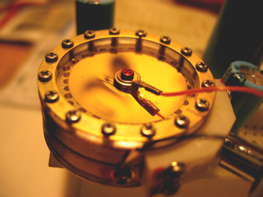
  As can be seen in the photo, I removed the inner layers of mesh on the first 9000, trying to get a better sound with the original capsule. I agree with all the people who say "Don't do that!". Now that I have a nicer-sounding capsule in there, I think the mic would sound better with the mesh back in, and the 2nd mic proves this, as I get it closer and closer to the other one. Also, the grill is weaker, and care must be taken when handling the mic not to deform it. Gus has already pointed all this out.
  If you buy one used, make sure it comes with it's 7-pin cable, as these can be expensive to replace.
  All in all, it's a pretty nice deal to get all the basic components of a cardioid tube mic for under $90, and it would be easy to alter the circuit to a more conventional design, if someone wanted to imitate a better-known circuit. Eventually, I will deal with the difference in grill mesh, and hope to have a nice stereo pair for under $200.
  Thanks for reading..


Attachments

  • 9000mods.jpg
    9000mods.jpg
    333.3 KB · Views: 221
This sounds like it is a different mic (cathode follower) and the schematic is no longer (or never was) attached, but the references in the text seem to suggest the same schematic:

http://www.gearslutz.com/board/gear-shoot-outs-sound-file-comparisons-audio-tests/664175-finding-m49-m249-mxl-9000-v76t.html

Stock, was one triode not used?

BTW, I'd posted on another forum about using 12AV7's in HST-11a's. The gain is about the same, maybe slightly slighly less vs a 12AY7, but I've not had a chance to compare the actual curves. Mmmmh. Cool. I may just give that a try. (I have a couple of those I want to do Dave Thomas' mod, just waiting for a parts order.)
 
Thanks. I hadn't seen that thread, and JJ is very generous with his upgrade info there. I might try that if these capsules prove too bright upon more listening. So far, I like them.
I see two schemos in that thread, and one of them is the exact same one posted above, which seems to be the stock circuit from my experience. The other one in the thread is for the M249, as a comparison. I understand why you are confused...
Either way, I think JJ and I would both agree, this mic is a nice platform for experimentation. I'm just more cheapskate about it. He has a reputation to maintain.
It wouldn't be too hard to convert these mics to almost any other simple tube circuit.
Eventually, if I like the mics enough, I might invest the sizable amount for top-notch caps and capsules, but I'll keep it cheap for the moment.
 

Attachments

  • Neumann-M249.gif
    Neumann-M249.gif
    18.6 KB · Views: 97
For whatever reason I didn't see the MXL schematic on that GS post when I was looking at it earlier today,  ??? must not have loaded the picture all the way. The text in the first post refers to a cathode follower being removed which is what made me wonder, as it isn't in either schematic.

I'm still waiting on those capsules, and the other order i have didn't come with mounts, so i'm waiting on saddles from Dave.

 
Yep, that's why I understand if you're confused. It  didn't make any sense to me either. Even so, a nice thread about the mic.
I still need to re-read, and look at the schemos more closely.
That's fine about the capsules. I won't have the money until the middle of next month anyway.
 
After reading your post I had to buy one. (got a 2010 too, for dany's u87 clone eventually,...)

Missing the PSU though. Looking at the schematic, it looks the same as the apex 460 w/o pattern, so I think I can try it out there. the heater wiring doesn't make sense though pins 5 and 9. ???? Also, the schemo (reversed engineered??? by ???) has one triode section, but the tube has all the pins going somewhere. I haven't looked closely, but are the triodes connected in parallel or a constant current whatever (see foxaudio -- it's kinda cathode follower. ) These things new are dirt cheap compared to the V76 which apparenlty is the same mic. A capsule upgrade, deleting the stuff after the transformer, change the tube this should sound pretty good. I want to change this so I can use my Royer PSU's so I'm likely to swap in a 5 pin XLR and change some of the resistors to account fo rthe lower b+.

 
Hi,
I have a cheap china semiconductor condenser mic, and it suffers this:
capsule.jpg

Is there any way to repair that? What affect does it have?
Thanks!
 
somorastik said:
Hi,

Is there any way to repair that? What affect does it have?
Thanks!

Can't say for certain what effect it will have. Not recommended to re-tension on your own. Replacement capsules are available at various price points.
 
Yep. Ditto to what Blue Jinn says. Probably sounds OK as is, but trying to re-tension will most likely destroy the capsule.
Replace it with another, if you don't like the sound.

@Blue Jinn
yeah, I probably should've kept this to myself, but I figured I have a pair and won't get any others, so why not share. Used price may go up if anybody reads this...
  I assumed the 2nd triode was grounded as in most plate-out designs like the Royer, C12, etc..., but as I have proven many times, I'm no genius about this, just brazen and curious.
  I like your plan. I'm sure there's some room for improvement in the transformer area, but I'm too broke at this point to go there. Sorry Cinemag, I'd love to send a lot of cash your way, but it'll have to wait. Would be nice to know the ratios on these trannies tho...
  Let me know if any info about the PSU would be helpful to you.

Ditto on brazen and curious. I figure it's only (a little bit) of money, and I'm no good at Soduko or crossword puzzles, I need to do something to keep my brain functioning... I don't have the necessary test equipment to determine the transformer ratio with any precision, I do have a signal generator, so I guess I could measure the AC voltage coming out the other side for a simple test tone.... That seems logical. 

OK, here comes my amateur mod suggestions:

Put in a 47 style unidirectional  capsule.

Remove all the stuff after the transformer. (R20/21; C20/21; L1/2)

Replace C6 and C6A with a 1uF polyester (I have a bag of those)

I don't get why R2 and R3 are used instead of one resistor. But, replace R3 with something like a 4.3M or so (or maybe get rid of R3 and replace R2 with a 2.2M) to use with a B+ of around 120v.

I do have a Big Ugly psu wired up that I can use with a 150v transformer I that puts out about 200v at a nominal 200k load. So I might test out some of this at the higher B+ first.

Same with you on the Cinemag and AMI. I'm guessing the stock trafo would be ok with some circuit changes.  Note that Dave Thomas has a 6.5:1 and a 5:1 transformer US$58 and $45.

Also, any idea what the transformer ratio is? My math stinks, I plugged in the plate resistor and a 12AT7 in an online calculator which says the output impedance is around 10k, so a 4:1 would give you 600 ohms, which may be a bit high.  AFAIK that is what is in the HST-11a (and AMI lists the 12AT7 on the T11 recommendations but they (AMI) also has    a (T13) 9.5:1 and (T49) 10:1 recommendations for a 12AT7 in addition to the T11 4:1, and Marik recommends a 10:1 for 12AT7 (CT10)

 
Looking at the schemo again, it would make sense to wire pins 5 and 9 at 6.3v for one triode section only. So maybe the other section is grounded. (Those wires must go somewhere.)

Also, plugging in a 12AX7 and 12AY7 into that same calc the impedance goes up quite a bit and a 4:1 wouldn't work.

http://www.ampbooks.com/home/amplifier-calculators/output-impedance/
 
  Sounds like a good plan. That's kinda what I like about these. They're simple, flexible, and one could easily turn them into almost anything they wanted.
  Your comprehension is obviously much better than mine. My only saving grace is that I was taught to read a schematic in my teens by an EE (my father), and only now am I really building on that. In short, I can't help much with the transformer calculations, but I know that info can be gleaned from somewhere on this forum.
  I'm assuming a 10:1 ratio would be what is needed, based on seeing similar circuits, tho this one is strange. One reason to use the Cinemag (2480?, my memory fails me at the moment) would be the humbucking bobbin-style, since we are removing all the RF interference network after the OT. I have one in my first Royer mic, and it sounds great, even with the stock 2001 capsule.
  Also, I'm working on the assumption that putting the proper tube in there helps to keep from over-driving the stock OT, and I'm using AV7s.... I need to do some serious recording with them to see how useful they really are. Unfortunately, DIY, sometimes takes up the time I should be using to compose and record...
    I found that the grill from the MXL 440 fits the 9000 just fine, so the sound is now closer for both mics. Doesn't look so hot, but I'll eventually find something that works better.
  Aha, thanks for that link. Came up while I was writing this. Guess I better check out the AV7 in there.
 
Took a quick look inside. The triode sections are completely paralleled. Plate wired to plate, grid to grid, etc. And the heaters in parallel also 4-5 tied together, 9 apparently to ground. Mmh. This lowers the output impedance by half if my research is correct, which now casts more doubt on the transformer. Also, the tube is rebranded, so who knows 12A?7. The impedance difference with the 12AX7 and 12AT7 seems quite a lot, although even 5k or so, I'm not sure a 4:1 would be enough, even with a 12AT7 at 5k or so, if you wanted a published output Z of 200 ohms. (It's late and that square root thing is confusing me right now.) If I'm calculating correctly you'd gegt about 300 ohm. A 5:1 would work to get 5k to 200.

It is odd too, as the C12 the other triode isn't used. . . Mmmh. The 12AX7 has about 4x the impedance of the 12AT7.
 
That's bizarre! The owners manual does indeed list output impedance at 200 ohms. So are we looking at a bogus, or incomplete schemo?
It might be best to just emulate the U47 or C12 circuit with one of these. Haven't had time to really understand the M249 schemo either, so you are now way out front on this.
My initial impression was good after the mods tho, so I'll stay where I am for now.
If you don't have the manual .pdf and want it, I'll put it up here.
 
somorastik said:
capsule.jpg

Is there any way to repair that? What affect does it have?
Carefully loosen the centre terminal screw.  The diaphragm will probably straighten itself.  Carefully tighten without moving the washer & solder tag as this is what caused the wrinkle in the first place.
Carefully put a drop of nail varnish/polish on the screw to stop it moving against the solder tag.  That's what the red on the screw is.
 
I haven't looked *that* close, but I'd suspect the schemo is accurate. The tube is paralleled at teh socket, so the pin diagram is technically accurate, it just doesn't show the connections at teh socket. Also, C6 and C6A are both clearly marked, and it looks about right. Thing is, just not sure about the transformer and the tube, as it isn't marked, and the 12AX7 is often substituted for some reason.  The AT and AX aren't *that* far off in gain (70 vs 100) but seem to be in impedance.  The 12AV7 seems to have a much lower output impedance too.  So, maybe just tube swap, C6 change and capsule change to start. I'm waiting on capsule mounts, and still waiting on the 47/67/12 order I made.

 
For output impedance, plate should be loaded with no less than 10x the output impedance of the plate stage.  So with 5K output impedance, you want at least 50K.  Driving a worst case input impedance of 150 ohms, you would need 18:1 ratio!  For 600 ohm input impedance, this falls to 9:1.

A 4:1 would load the plate with 9.6k, which means that roughly 40% of your signal would be thrown away when driving a 600ohm input.  However it might be ok with a 4:1 if you were driving a higher differential impedance input like a DAC.
 
The 200V B+ makes sense if both triodes are being used, but I can't say I've seen that so far in any designs I've looked at. Doesn't that mean the heater should be @12V?

Thanks for the info Matador. Still trying to absorb and understand. Lots of reading to do.

Patiently waiting for the capsules Blue Jinn. In my case the longer it takes, the more prepared I will be financially.
It will most likely go in my Big Ugly/G7 mic. The capsule in there now is bright, but incredibly clean. Could also be the OT causing some of that.

If this thread is showing me anything, it's that it's high time I get the comprehension of these circuits you all seem to have so I can balance them properly.
This info is all here somewhere. Just gotta go look for it and read.
 
The heater on 12A*7 tubes has 3 connections. It can be wired in series at 12v/150mA or in parallel at 6.3v/300mA.  AFIAK it doesn't much care, as either way, each heater (for each triode) gets 6.3 volts.

As for the 200v B+ I just don't get it. The G7 pushes it up to 160v. But most other designs I've seen are around 100-120v. I don't think it matters that there are two triodes vs one.

@matador: thanks!
 

Latest posts

Back
Top