[BUILD] CAPI VP28~500 Series~2-Stage Preamp~Official Support Thread

GroupDIY Audio Forum

Help Support GroupDIY Audio Forum:

This site may earn a commission from merchant affiliate links, including eBay, Amazon, and others.

jsteiger

Well-known member
White Market Member
Joined
Apr 11, 2008
Messages
3,506
Location
Nashville TN
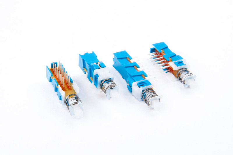
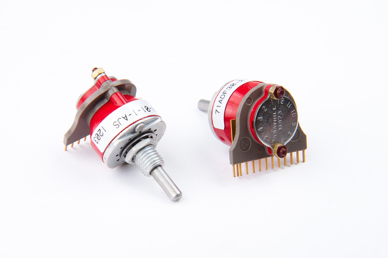
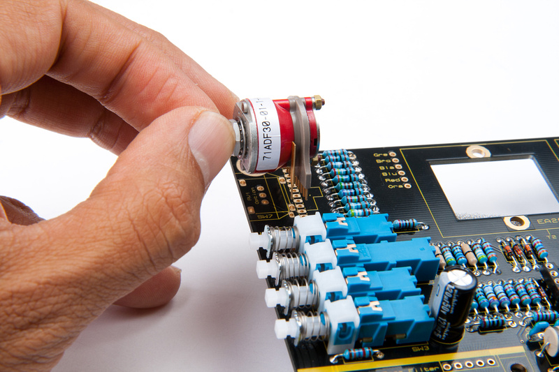
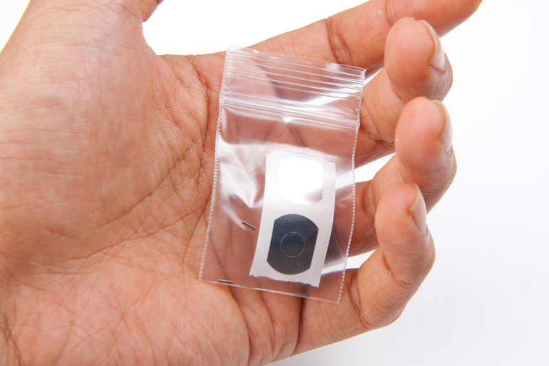
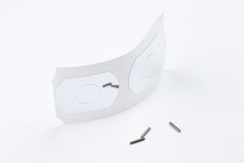
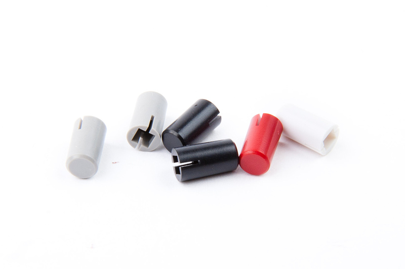
***ATTENTION!! The VP28 kits are now shipping with Grayhill switches that have factory set stops. This means there will be no stop-pins or stickers shipped or required. A quick glance at the switch should give this away as there are no holes to put the stop-pins in!!***

Since the kits have started shipping, it's time for the support thread!  :)

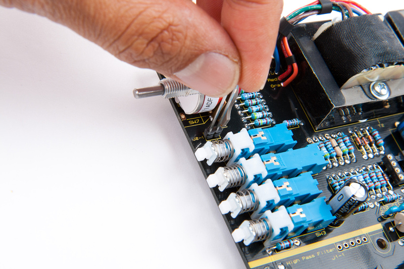
**This is a somewhat complicated build. Harder than a VP312DI but easier than a Love Child. I recommend reading completely thru the Assembly Aid before starting on anything. There are some points made in the doc that can save you much time and prevent crucial errors during the build.

--------------------------------------------------------------------------------------------------------
September 21st, 2015 Update:
All support docs for this project can be found on the recently added
Support Docs page at www.capi-gear.com
--------------------------------------------------------------------------------------------------------


--------------------------------------------------------------------------------------------------------
March 18th, 2016 Update:
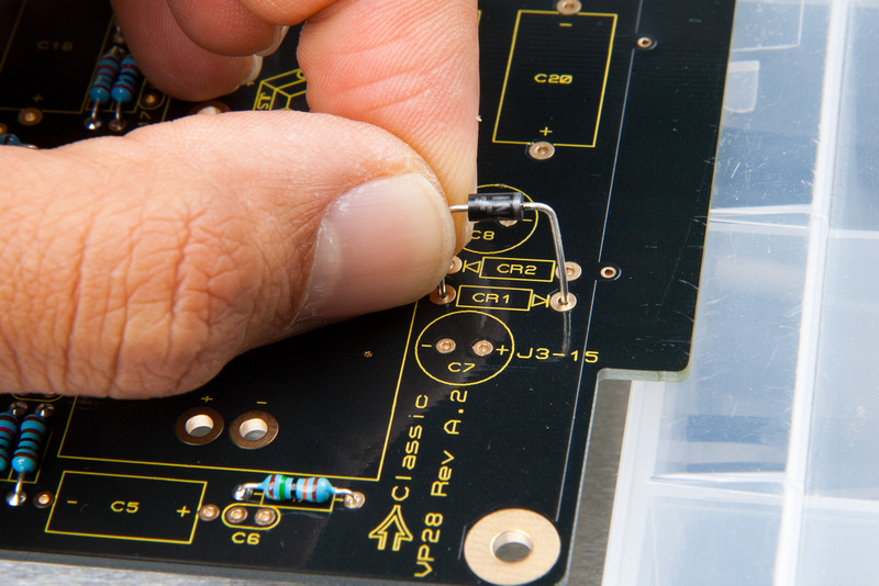
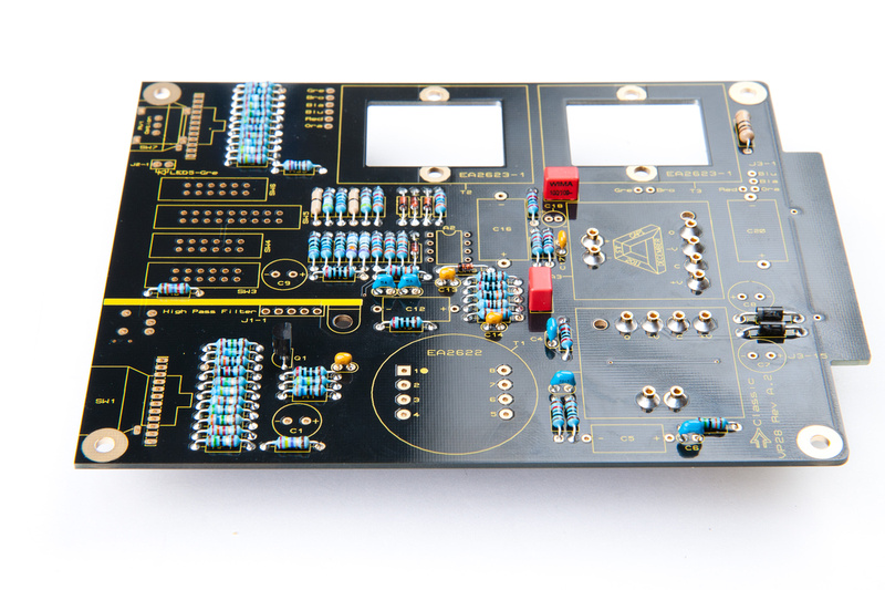
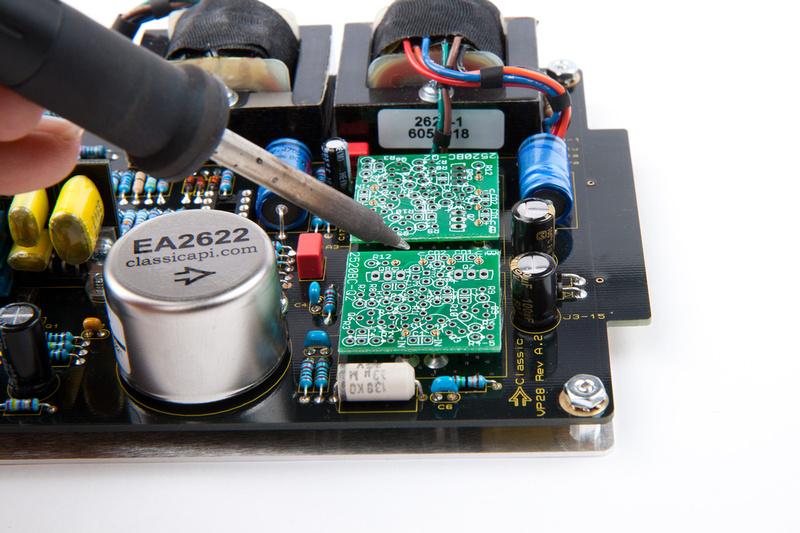
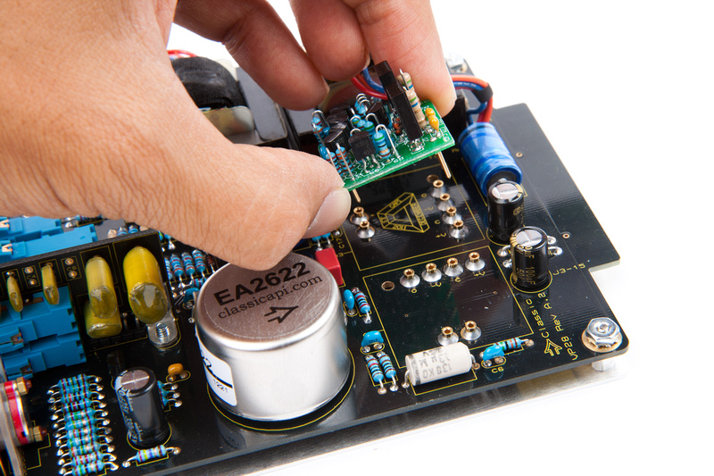
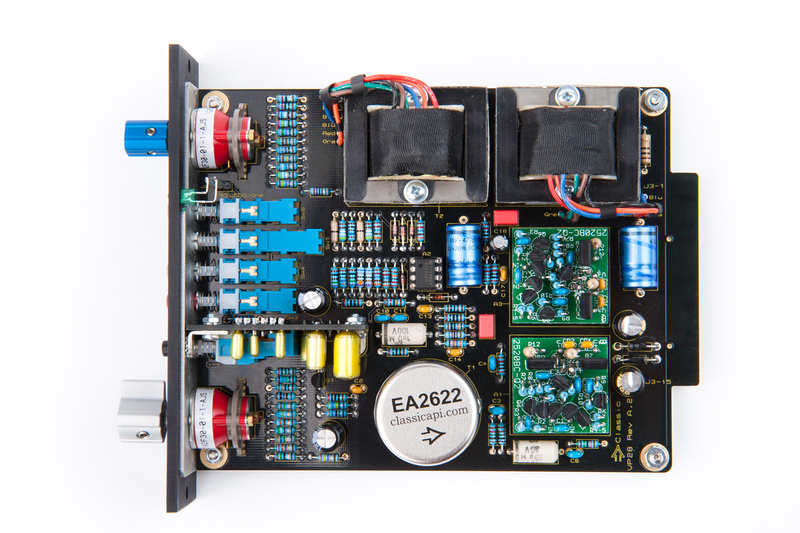
Rev B boards are now shipping for the VP28. To easily identify, the Rev B boards are green and they have the CAPI® label affixed. To find out what has been changed, please read the
Rev B Addendum. Like with all projects, it is crucially imperative that you follow the BOM that matches the revision of the PCB that you are building.
--------------------------------------------------------------------------------------------------------


Some details can be found here http://capi-gear.com/catalog/product_info.php?products_id=318

temp-VP28.jpg


Cheers, Jeff
 
Sorry for the low quality of the following pics. I know 'Chung's work will make me want to take these down but until he gets them done, these will have to do.

Just click the thumbs to enlarge!!  :)

Finger tight hardware on the 553F-Sub-HPF PCB, top view.


Finger tight hardware on the 553F-Sub-HPF PCB, bottom view.


553F-Sub-HPF PCB, lightly snugged into position on the main PCB.


The important thing in this crappy pic, is to note the outside tooth lock-washer placed between the VP28 L-bracket and the small Keystone bracket.


The 4-40 x 1/8" undercut flat head screw tightened thru the front of the VP 28 L-bracket.


After final adjustments and a tightening of the HPF board's fasteners, it's time to solder the 5-pin header thru the access slot in the L-bracket.


Recommended bending and installation of the four LED's on the main PCB.


Recommended bending and installation of the signal present LED onto the long 2-pin header.
 
OK. . . as is customary in the Chinese Labor Camp, I waited a few weeks after receiving this package from jsteiger. . . you know.  To keep people guessing about delivery time-frames.  But, at some point, you need to begin cryptic communications in broken english allegedly for technical clarifications. . . then, of course, ignore those clarifications and do what you were going do anyways. . . ok.  It may be a bit too late in the evening to be typing so I'll just start posting pictures  :eek:

Let's see what's in the box, shall we?

p791294435-4.jpg


Another fine kit from Classic Audio Products of IL.  In keeping with the new no-nonsense anodized black look, this kit looks well laid out and intuitive to assemble.

p752592215-4.jpg


This build will feature the stepped grayhill gain switch option, so we begin by sorting the resistors for the gain switch and fader.

p932589790-5.jpg


Carefully bend the leads and install resistors to their designated positions.

p989712091-4.jpg


Bend the leads to hold resistors in place, flip the board over onto a nice, flat surface and solder from the back side of the PCB.

p868887612-4.jpg


. . . and trim the leads when finished.

p596887611-4.jpg


My aim with heat settings on my temperature-regulated iron is to limit the time the iron is actually on the component/PCB. I also try to  apply just the right amount of solder  to flow a smooth bead  that carries through a little bit to the top side of the PCB. . . all in the shortest amount of time practical so as not to damage the components.

p628963692-4.jpg


Next, sort the remainder of the resistors for the main PCB as well as the transistor and diodes.

p138286483-5.jpg


It's worth noting even though all of the small diodes on this PCB are the same that the tiny markings on the 1N914 diodes read:

91
4B

It doesn't hurt to confirm.
p775789131-3.jpg


Populate the resistors,

p94591274-4.jpg


p471308580-4.jpg


p535610363-4.jpg


and install diodes.  Orientation is important on the diodes.  Make sure the side marked with a solid stripe corresponds to the arrow screen-printed on the PCB.

p449490756-4.jpg


Diodes are populated.  Double check to confirm orientation is correct on all of these.

p91854723-4.jpg


Install Q1 transistor next.

p128573896-4.jpg


Next, locate the bag that contains hardware.

p975531190-4.jpg


And locate the Millmax sockets for the 2 DOA's.  Watch out.  They like to roll on the floor.

p612716117-4.jpg


Insert these from the back side of the PCB.

p764894441-4.jpg


Set soldering iron temp a bit on the hotter side and solder.  We want a little bit of solder to bleed over to the front side

p601792772-4.jpg


but not quite as much this. . . oops.  It's still ok. . . just not as pretty as it should be for an instruction set.

p1064636930-4.jpg


Next, sort the capacitors for the main PCB.

p784387212-5.jpg


and watch out for the markings on this little bugger.  68pF.

p787588576-4.jpg


And populate the capacitors.  I start from the short ones and work my way up to the tall ones, but it doesn't really matter what order.

p578734400-4.jpg


Before I got to the larger electrolytics, I pulled the IC socket.

p195084987-4.jpg


p291599270-4.jpg


Next, install the electrolytic capacitors.  Polarity is important on these. The solid line indicates the "-" side of the capacitor.

p495819353-4.jpg


on the radial caps, the longer of the legs is the "+" side.  Also, the solid line indicates the "-" side.

p198881582-5.jpg


Caps installed.

p17486801-4.jpg


Next, pull these switches.

p396753335-4.jpg


And install onto the PCB

p33195728-4.jpg


Solder one pin and then check alignment with the screen printing on the front side of the PCB.  Make sure the switches are sitting flush to the PCB and are aligned as straight as possible.

p164345028-4.jpg


p207958885-5.jpg


Solder in the rest of the pins after verifying alignment and making adjustments.

p317477388-4.jpg


repeat for the other 3 switches.

p50157258-4.jpg


Next, pull this toggle switch.

p425777670-4.jpg


SW2 fits on the back side of the PCB.

p220017668-4.jpg


IMPORTANT!  Before soldering in these pins, clip the leads close to the PCB.  The high pass filter board that goes directly above this switch will interfere otherwise.

p274956165-4.jpg


Solder after trimming the leads close.

p331724523-4.jpg


Next, pull the 2 grayhill switches.

p34608117-4.jpg


And install.

p467191070-4.jpg


Solder 1 pin only and confirm that the switch is positioned tight to the PCB and properly aligned.

p402015233-4.jpg


Install the 2nd grayhill switch and do the same.  Solder 1 pin and adjust for perfect alignment.

p526582912-4.jpg


p140354419-4.jpg


When satisfied with the alignment, solder in the rest of the pins.  Be careful not to use too much solder and bridge the contacts.  If necessary, verify with a magnifying glass that the solder joints are clean.

Next, pull the stop pins and retaining stickers.  Be careful, if these pins fall on the floor, they may very well never be recovered.
The Grayhill switches now have factory set stops. There is no need for the stickers or pins.

p220638540-4.jpg


p400895034-4.jpg


Install stop pins at the 12:00 position.
The Grayhill switches now have factory set stops. There is no need for the stickers or pins.

p407292101-4.jpg


p137026114-4.jpg


And install stickers to retain the pins.
The Grayhill switches now have factory set stops. There is no need for the stickers or pins.

p413136204-4.jpg


Next, pull the EA2622 input transformer.

p35489124-4.jpg


Note the dot on the sticker on the transformer.  This indicates pin one.  Align pin 1 with the dot silk-screened on the PCB.

p199652547-4.jpg


Install a piece of double-stick foam tape.

p138742287-4.jpg


And install the transformer.

p461373371-4.jpg


Next, pull the hardware to install the 2 output transformers.

p207673396-4.jpg


And pull the output transformers.

p370589465-4.jpg


put a flat washer on 2 of the long screws.

p506992195-4.jpg


Install screws on the transformer.

p128037712-4.jpg


flip the transformer over and install another flat washer which will sit between the PCB and the transformer.

p449833032-4.jpg


And place the transformer on the PCB.

p23062364-4.jpg


Install lock washers.

p150515559-4.jpg


And then nuts.

p458001930-4.jpg


Tighten from the top side with a phillips head screwdriver.

p310494026-5.jpg


And repeat for the 2nd output transformer.

p373815489-5.jpg


p283959566-4.jpg


Align both transformers with the screen printed boxes on the PCB and tighten them down.

p179460339-5.jpg


Carefully trim the leads to length, strip and tin the tips, and organize with some short strips of shrink tubing.

p318927929-4.jpg


And begin installing the transformer leads to their corresponding labelled terminals on the PCB.

p101271502-4.jpg


p734912231-4.jpg


p861186041-4.jpg


and repeat on the other transformer.

p700565917-4.jpg


p805597173-4.jpg


iron is installed.  IMagine how many kits Jeff could sell if there could just stay in stock  ;D

p543742248-4.jpg


Next, locate this long header.

p999536018-4.jpg


And install onto the PCB.

p929355217-4.jpg


Solder 1 pin and align tight to the PCB and perpendicular.  After everything looks aligned, solder the other pin.

p796276218-4.jpg


Next, sort the components for the HPF PCB.

p540148853-5.jpg


Install the L-header first.

p692615761-4.jpg


I used a clamp to secure the header while leaving one pin exposed on the side.

p976293751-5.jpg


And solder that exposed pin first.

p712104993-4.jpg


Then, shift the clamp to the other side and solder the opposite pin.

p1035821172-4.jpg


With the header tightly secured, solder the remaining pins.  OK. . . the method may be over-complicated, but it gets the job done.

p769252670-4.jpg


Pull push-button switches for the HPF board.

p1038349874-4.jpg


And place onto the PCB.

p803661890-4.jpg


Solder 1 pin on each switch.

p908572716-4.jpg


And verify alignment on the front.  Adjust as necessary before soldering in the rest of the pins.

p1049592930-4.jpg


p843221392-4.jpg


Next, populate the electronic components.

p634517385-4.jpg


p881329648-4.jpg


p547309329-4.jpg


Pull mounting hardware for the HPF PCB.

p1065280830-4.jpg


And install the brackets finger-tight only at this point.

p616526251-4.jpg


Lock washer goes on this side.

p542338315-4.jpg


Followed by the nut.

p897526962-4.jpg


Repeat on the other side.

p639452394-4.jpg


And the HPF PCB is assembled.

p882493705-4.jpg
 
Next locate the caps for the pushbutton switches.

p813059182-4.jpg


The pair of black ones go on the high pass filter PCB that was just assembled.

p1030477851-4.jpg


p636649762-4.jpg


And the rest go on the main PCB.  Red (48v phantom power), gray, white gray in that order.

p580947450-4.jpg


p631655237-4.jpg


p704049382-4.jpg


Next, pull hardware to mount the main PCB onto the L-bracket.

p1041379994-4.jpg


Start by inserting the screws from the bottom of the L-bracket.

p763691624-4.jpg


Tighten the rear standoffs all the way and install the front 2 half way only so the PCB can slide over and into position.

p682278055-4.jpg


p903019152-4.jpg


Pull Hardware to set the high pass filter PCB onto the main PCB.

p701091397-4.jpg


Install the lock washer onto the screw.

p667510283-4.jpg


Set the HPF PCB onto the main PCB.

p992046542-4.jpg


And attach from the bottom with the screw/lock washer.  Finger tight will do right now.

p752418553-4.jpg


Carefully slide the main PCB assembly onto the L-bracket.

p762740056-4.jpg


Pull hardware to set the main PCB.

p766201430-4.jpg


Align the front of the PCB snug and square to the L-bracket and install rear star lock-washers and nuts.

p609588712-4.jpg


p770141067-4.jpg


p1073296460-4.jpg


With the PCB in position, we can now tighten down the front standoffs.

p896009807-4.jpg


And install the small lock washers and nuts onto the front screws.

p907679446-4.jpg


Verify that the main PCB is square to to the L-bracket and tighten all 4 nuts.

p844588191-4.jpg


Pull hardware to mount the front of the HPF PCB onto the L-bracket.

p562111426-4.jpg


Insert the star lock washer between the L-bracket and the HPF PCB assembly like this.

p984297369-4.jpg


And insert small screw from the front and tighten down.

p996513207-4.jpg


p1063367388-4.jpg


Locate the front panel and install.

p680683943-5.jpg


Align the front panel to the 4 main PCB pushbuttons and to the L-bracket.  Then, install the 2 grayhill switch nuts (discard the Grayhill switch lock washers).

p846883663-4.jpg


p1052233172-5.jpg


Next, adjust the HPF PCB so the pushbuttons are aligned with the front panel.  The screws holding this in should only be finger-tight at this point so the board can move.  When happy with the alignment, tighten down these 3 screws to lock the HPF PCB into position.

p829506208-5.jpg


p585062499-5.jpg


p820391736-5.jpg


From the cutout on the back side of the L-bracket, solder the HPF PCB header to the main PCB.

p997686912-5.jpg


Next, pull the 5 LED's.

p760665849-4.jpg


Cut and bend the leads like this.  I chose to retain one short pin and one long pin when I cut the LED just for personal reference.

p978545259-4.jpg


Carefully position one red and 3 yellow LED's onto the main PCB from the bottom of the L-bracket.

p546885776-4.jpg


p764394820-4.jpg


Notice the short leg of the LED's correspond to the silk-screened arrow mark.

Once happy with the LED positioning, solder the leads to the main PCB pads.

p661338723-5.jpg


p566612407-4.jpg


Pull the 2 clear sections of heat-shrink tubing.

p746068427-4.jpg


cut these to reveal about 1/8" and slide them over the tall jumper near the front panel.

p1059666512-4.jpg


Next, connect the green LED to this jumper.  Some bending will be involved.  Please excuse my mis-matched shrink tubing.  Shortly after taking the previous photo, I must have accidentally flung the supplied tubing piece across the room when putting the camera down and I could not find it, so I had to use another one from my kit which was not the same diameter.

p581449958-4.jpg


The LED will end up looking something like this.

p540796405-5.jpg


Make sure the short end of the LED corresponds to the silk-screened arrow mark on the PCB for this LED just like the others.

Carefully position the green LED and make any final tweaks necessary for a tidy fit.

p677794546-4.jpg


And solder into position.

p742873606-4.jpg


p780309118-5.jpg


Next, I used some water on a Q-tip to clean off some of the residue left on the faceplate from installation.

p649975468-4.jpg


Pull knobs and shaft adapter.

p924151495-4.jpg


Use pliers to position both knobs in the 12:00 position (pointing straight up), and position the shaft adapter so the gap is facing down.

p985764448-4.jpg


Press the adapter onto the Grayhill switch shaft until somewhat flush with the top of the post.

p553143808-4.jpg


Install knobs.

p596472635-4.jpg


Next, pull the 2 colored stickers that go on top of the knobs.

p687640079-4.jpg


Peel off the paper backing and install.

p865520473-4.jpg


p682302058-5.jpg


For this build, we will need 2 opamps.  I chose to use Gary Barnett's GAR2520 op amp kits for this build.  These are fast becoming my go-to op-amps for API-type builds and sound phenomenal.

p862851650-4.jpg


Pull the pins from the kits.

p149248189-4.jpg


and insert into the opamp sockets of the main PCB.  This positions the pins perfectly for soldering and also loosens up the sockets that can be extremely stiff the first time an opamp is inserted.  It is much easier to insert the pins one at a time like this.

p365954996-4.jpg


p262063099-4.jpg


Place the GAR2520 PCB's onto the pins and solder in place.

p116346179-4.jpg


Pins are perfectly aligned and the op-amps are ready to be populated.  The documentation provided with the GAR2520's is VERY thorough and walks you step-by-step through the process.  A steady hand and an eye toward detail are required.  I will populate a pair to the best of my current ability.

p265724066-4.jpg


p311115191-4.jpg


p335779515-4.jpg


p239965264-4.jpg


p475967697-4.jpg


p155640111-4.jpg


p515875232-4.jpg


p143924925-4.jpg


and opamps complete.

p501593375-4.jpg


p475041548-4.jpg


p88392839-4.jpg


Next, pull the IC that drives the green signal LED.

p263947075-4.jpg


and carefully insert into the socket on the main PCB making sure to align the dot with the notch on the socket.  Do not press the IC into position until you are absolutely sure all of the delicate pins are properly positioned in the socket.

p30990011-4.jpg


Note the IC's orientation.

p275207808-4.jpg


Next, install the 2 GAR2520 opamps or the +, -16V opamps of your choosing on the main PCB.

p302477476-4.jpg


The VP28 is now complete.  Humans win. . . again.  If all went well, it should run right out of the gate.

p508029591-4.jpg


p200759318-4.jpg


p15083809-5.jpg


p319296452-5.jpg


I sincerely hope you've enjoyed this installment of "Build Jeff's Stuff' as much as I have and find this photo documentary helpful  ;D
 
park place & boardwalk...

this comment box is now for sale.

Thanks for looking...


to the mods, this is only a joke.
 
bigevil said:
park place & boardwalk...

this comment box is now for sale.

Thanks for looking...


to the mods, this is only a joke.
Ouchy ouch!! Man that was Big....and Evil

So how much you want for it?

Haha, also a joke  ;) ;D
 
wow, love the metalwork, especially the undercut screw hidden behind the front panel. impressive.
 
Got my first one built.  Took around 4 hours but I think I can do my other one faster.  I built the 4 opamps while I was waiting on the 28s to get in stock so that helped.  Anyhow, just tested everything on it, and everything works, first try!  Won't try it out on some tracking till probably next week though  :(  I think the hardest part for me was getting the LEDs in there right, but even that wasn't bad.  Might just be bc its 5 in the morning and I need to go to bed.
 
J Adams said:
...Anyhow, just tested everything on it, and everything works, first try!
Excellent news! Congrats!  8)

...I think the hardest part for me was getting the LEDs in there right, but even that wasn't bad...
They can be a little tricky the first time. After building a few dozen, I fly thru them in no time.  ;)
 
I hit  2 very minor snags building the second one (my own fault), but still got it done in about 3.5 hours.  Again, everything works on it, first try.  Great design on the boards Jeff, can't wait to see how these fair in my sessions next week.  Even though they take a lot longer than the 25s and 312s I built, I think it was more fun as well.

Oh, and the reason I have both big knobs on one is because I don't have a small enough allen wrench for the small knobs but I wanted to at least test them both out.
 

Attachments

  • photo-1.JPG
    photo-1.JPG
    815.8 KB · Views: 292
Looking good man!  8)

What were the snags? Maybe it could help someone in the future not fall in the same rabbit hole.
 
gevermil said:
When is the Entire Bundle avalible
They were available late last week but I was cleaned out of 2623-1's in a about a day. I have another batch being shipped out this Thursday so I should have them in hand Friday. That will put the VP28's "in stock".
 
I really don't remember, other than thinking some things were taking me longer than they should have bc I was tired.

What size allen wrench does the top knob use?  I have a ton of allen wrenches here but none small enough.  Stopped by WalMart after work tonight (only place open at 1AM) and they did't have anything smaller than what I have. 

These preamps (and gar2520s) are the only thing I have ever built or soldered.  I am glad I started with the 25s/312s before attempting the 28, and I thought even though the assembly guide was not as thorough as the other one you did, between that and the BOM I was perfectly fine and felt very comfortable with everything. 
 

Attachments

  • photo 2-2.JPG
    photo 2-2.JPG
    760.3 KB · Views: 394
J Adams said:
What size allen wrench does the top knob use?  I have a ton of allen wrenches here but none small enough.  Stopped by WalMart after work tonight (only place open at 1AM) and they did't have anything smaller than what I have. 

Most set screws on knobs are 1/16" – it was a bitch for me to find one of those in Europe since it's right between 1.5mm and 2mm, and none of them will work  :mad:

Nice set of preamps you have there :) Can you describe the sonic differences?

-toby
 
J Adams said:
...What size allen wrench does the top knob use?...
The small 3/8" blue pointer requires a .05" Allen wrench. The larger 1/2" clear pointer is 1/16". You will probably need to visit an Ace Hardware or something more "specialized" than Wal-Mart.  ;)

I am surprised that Imperial sizes are not readily available in the UK. I can go to any hardware store here and buy Imperial or Metric anything. Bastards.  :mad:

BTW, nice lunchbox!  8)
 
Both of mine worked on the first try too. If you read the manual first and take your time it's very straight forward. The only "mistake" I made was using the wrong type of washer on some screws. Cheers Jeff- Thank you for your hard work!
 
Great job on this one, Jeff!  Successful build, took a few evenings of an hour here and there.
(only 1 leftover washer, and couldn't seem to find two lock washers, but I probably shouldn't build these things late at night!!)

In the studio now, comparing it to my other pre's... Enjoying it so far.
Thank you thank you thank you for the signal indicator LED!!!

-Chris

EDIT:  *love* it on guitar. driving the preamp gain hard results in some happiness. :)
 

Attachments

  • Untitled.jpg
    Untitled.jpg
    107.1 KB · Views: 183

Latest posts

Back
Top