This is not correct, they are marked in 2 ways. There are a series of arrows with a "-" inside each arrow running down the side pointing to the negative end. The positive end has a groove running around it. This is true for nearly all of the BC/Vishay axial caps.discord said:It seems these new C12 caps (the blue ones) have no positive or negative markings.
You are using an out of date browser. It may not display this or other websites correctly.
You should upgrade or use an alternative browser.
You should upgrade or use an alternative browser.
[BUILD] CAPI VP28~500 Series~2-Stage Preamp~Official Support Thread
- Thread starter jsteiger
- Start date


Help Support GroupDIY Audio Forum:
This site may earn a commission from merchant affiliate
links, including eBay, Amazon, and others.
Hi, I wonder if anyone can point me in any direction...
After finishing my build, I have VERY quiet audio with a mic and no signal present LED at any time.
All of the other LEDs appear to work correctly. I have an audix i5 connected, and both pots have to be cranked to get anything.
I don't have a way to do the tests with power connected, but when testing the resistance on the DOA sockets, all measurements are correct except between v+ and c. For both sockets, this resistance measures exactly the same: 4.06 k ohms.
I'm going through and re-flowing the solder everywhere and checking everything with a magnifying glass. I hoped with my symptoms someone might be able to help me focus on a particular area of the board.
I also double-checked every diode and cap to make sure they were installed the right direction.
One mistake I may have made was soldering the transistor all in one shot. Would a fried transistor show these symptoms?
I'm going to do the line level test now so I have actual numbers.
Golgoth
Well-known member
Are you using known to be working opamps? Did you try switching their position? I had almost the same problem except I had NO audio at all. One transistor was backwards on the DOA used for input.
thanks for the reply.
Yes sir, my two red dots came to me already assembled. I do have an opamp in my tonebeast that I can pull out for troubleshooting though if it still seems like a good idea.
I reflowed the solder everywhere but the same symptoms persist. I did remove the opamps and the IC before soldering, so they were re-seated before I tried again. But after it was reassembled before I tried it out I still get that 4.06k ohm reading when I measure the opamp sockets between "+v" and "c". And the reading is exactly the same for both opamp sockets.
I did not reflow the solder on the hpf board though. I will do that as well. I saw in another post that the audio goes through there no matter what, right?
Also, one point that I don't have a lot of confidence in is the soldering of the wires from the transformers. I had a difficult time with these. I will give them special scrutiny when I take the hpf board off.
I'm definitely planning on buying one of those diagnostic extension cables when the capi store is open again.
thanks for your help.
one more question actually - I am for sure a novice. I only built a few simple things before. I was trying to find a spec on a good temperature to be soldering this project. It might seem like an obvious question but what is a good setting? I was working most of the way through the project at 713. I hope that wasn't stupid, and I was careful not to touch a spot on the board for more than about five seconds. When I went back over the board I bumped it up to 730 so I wouldn't have the iron on the board too much..
Thanks.
Golgoth
Well-known member
I'm a novice too actually, I just built my first kit (VP28 ;D + DOAs + power supply) two weeks ago. The symptoms were the same.
If you ordered your red dots from CAPI I don't think opamps are the problem here tho it's worth nothing trying with other ones in different configurations. Maybe you could post HD pictures of the board? This could very helpful.
713°F is right for electronics. You can even go down to ≈ 650°F (as I did) if you're using quality lead solder.
Wait for Jeff to read your message, he will help you for sure.
Thanks.
I went through and re-flowed the solder on the hpf board and the wires for the transformers... now i have sound at full volume and signal light!
I was trying to test the hpf function with the line in but it doesn't seem to be working. Should the hpf work in line in mode? My test consisted of changing my 1K test tone to 30hz and checking if the signal lowered with the hpf buttons in - which it didn't.
I also have a problem where my polarity flip button completely shuts off the signal, so I'll have to re-solder that I imagine.
Thanks for your help.
discord
Member
- Joined
- Jul 11, 2014
- Messages
- 18
jsteiger said:This is not correct, they are marked in 2 ways. There are a series of arrows with a "-" inside each arrow running down the side pointing to the negative end. The positive end has a groove running around it. This is true for nearly all of the BC/Vishay axial caps.discord said:It seems these new C12 caps (the blue ones) have no positive or negative markings.
Ah, didn't realize that's what that was. Thanks!
Anybody tried 990c opamps in the VP28? Is it cool/worth trying? What's it sound like?
sumyungdon
Member
Greetings!
I have just completed the VP28 kit, and am having some issues. Firstly though, I would like to say thank you Jeff for a great, extremely well-documented, and fun kit! And thank you Chunger for an excellent in-depth visual build guide! I have done a few kit-based DIY projects (Hamptone, Five Fish, Seventh Circle, Hairball...) and this one was impressively straightforward with detailed documentation. Had a blast.
Now my problem is, the preamp is passing a signal (a fine sounding one, at that) perfectly fine for dynamic microphones. All of the LED's light up and the HPF works well to my ears. Very badass with a good dynamic. However, when I engage the phantom power switch, it ceases to pass a signal for a condenser mic - instead hissing a white noise. There are some pops and bumps, and the signal LED lights up sporadically, but overall no signal and just fuzz. Regardless of the MIC button being depressed or not - and when the PAD becomes engaged, the noise turns to more of a buzz. I am using pre-assembled red dot opamps.
I tried the obvious - switched cables on all ends, switched microphones, changed interface channels for monitoring. The rack I am using is the classic api vpr eleven space rack - and I just assembled the rack and power supply. I double and triple checked the rails and have confirmed that the voltages are correct on all of the card edge connectors. I tried swapping the VP28 to a different slot, same issue. So I am thinking, somewhere along the line, the +48v supply is getting adulterated after hitting the receptor on the card edge. I tested with my multimeter to confirm continuity between the traces leading from the bottom pin receptor, all the way to the phantom power switch.
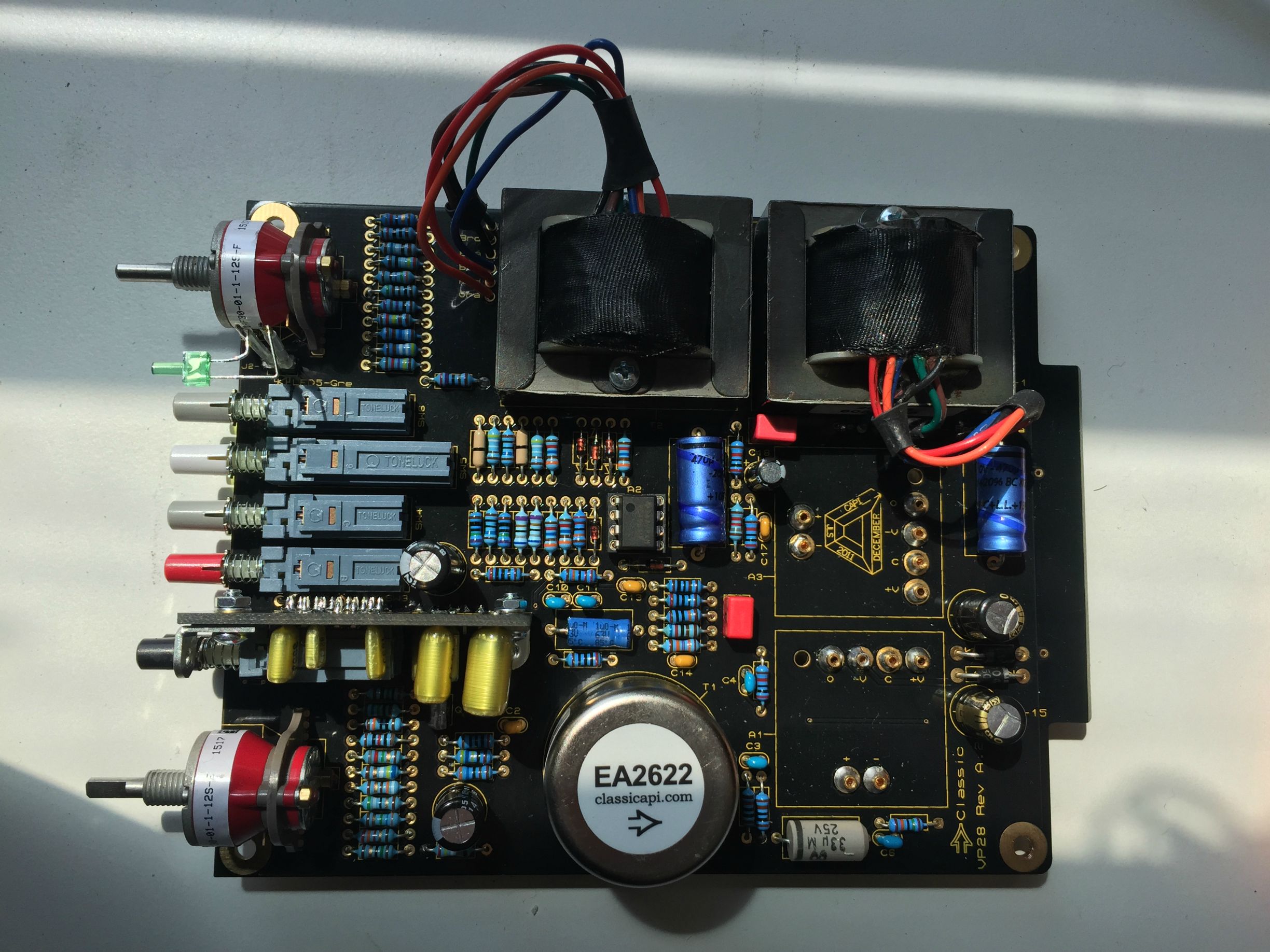
I am not really sure what the issue could be here - I am pretty novice when it comes to the theory and understanding of these circuits, and cannot find a schematic for this project. This is actually the first project I have ever had to troubleshoot - all the rest worked well out of the gate - and frankly I'm excited to finally be "forced" to learn something deeper than proper placement and soldering/assembly technique. That being said, I don't know where to start. Attached a pic, in case anybody can spot something I have missed. I'm pretty confident in the placement of the components. Could this be caused by C9, or R15-R24? I'm not even sure exactly how to confirm that the switch is working properly, mechanically. I have scoured this support thread and can't seem to find anyone else with the same issue. If there's anyone out there who might shed some light, any help is greatly appreciated!
Thanks!
Andrew
I have just completed the VP28 kit, and am having some issues. Firstly though, I would like to say thank you Jeff for a great, extremely well-documented, and fun kit! And thank you Chunger for an excellent in-depth visual build guide! I have done a few kit-based DIY projects (Hamptone, Five Fish, Seventh Circle, Hairball...) and this one was impressively straightforward with detailed documentation. Had a blast.
Now my problem is, the preamp is passing a signal (a fine sounding one, at that) perfectly fine for dynamic microphones. All of the LED's light up and the HPF works well to my ears. Very badass with a good dynamic. However, when I engage the phantom power switch, it ceases to pass a signal for a condenser mic - instead hissing a white noise. There are some pops and bumps, and the signal LED lights up sporadically, but overall no signal and just fuzz. Regardless of the MIC button being depressed or not - and when the PAD becomes engaged, the noise turns to more of a buzz. I am using pre-assembled red dot opamps.
I tried the obvious - switched cables on all ends, switched microphones, changed interface channels for monitoring. The rack I am using is the classic api vpr eleven space rack - and I just assembled the rack and power supply. I double and triple checked the rails and have confirmed that the voltages are correct on all of the card edge connectors. I tried swapping the VP28 to a different slot, same issue. So I am thinking, somewhere along the line, the +48v supply is getting adulterated after hitting the receptor on the card edge. I tested with my multimeter to confirm continuity between the traces leading from the bottom pin receptor, all the way to the phantom power switch.
I am not really sure what the issue could be here - I am pretty novice when it comes to the theory and understanding of these circuits, and cannot find a schematic for this project. This is actually the first project I have ever had to troubleshoot - all the rest worked well out of the gate - and frankly I'm excited to finally be "forced" to learn something deeper than proper placement and soldering/assembly technique. That being said, I don't know where to start. Attached a pic, in case anybody can spot something I have missed. I'm pretty confident in the placement of the components. Could this be caused by C9, or R15-R24? I'm not even sure exactly how to confirm that the switch is working properly, mechanically. I have scoured this support thread and can't seem to find anyone else with the same issue. If there's anyone out there who might shed some light, any help is greatly appreciated!
Thanks!
Andrew
Attachments

kante1603
Well-known member
Hello and welcome to the forum.
May I ask if you have the ground jumpers set?
Phantom power uses the mic cable shield ( pin 1 on the xlr) as a return path,so it is absolutely necessary to have the jumpers set to ground for each slot where you will have phantom powered devices on.
Since the preamp seems to work o.k. with a dynamic mic it might be something simple like that.
Just a thought,
best,
Udo.
Edit:Some minutes ago I've seen that the rack design has changed,mine all have headers to place jumpers for any possible connection for the pin 1 on the xlrs,or to even leave them open.
You can still check continuity from the xlrs on the back to the corresponding pins on the edge connectors,best done with the rack unpowered to prevent shorting pins with the probe.
This way we can sort out wether you have a problem with the preamp or the rack/psu.
I'm on holidays atm and don't have a module or docs accessible,sorry.
sumyungdon
Member
Udo - thank you for the reply! I appreciate the reply while you are on vacation. I understand Jeff is out of town as well so I am exercising my patience on this one
Your edit is correct - my rack does not have jumpers for the XLR connectors. Mine has a date stamp of November 2013 for the design. However, I did not solder jumpers on the XLR pins when I assembled the rack. It is something that now you mention, could likely be the issue - on all the other kits I have built, it has been necessary to solder a jumper between certain pins on the XLR jack. I have checked continuity between XLR pins (to the microphone) and the pins on the card edge connector. They are as follows:
XLR pin 1 - continuity ONLY to card edge pin 1
XLR pin 2 - continuity ONLY to card edge pin 10
XLR pin 3 - continuity ONLY to card edge pin 8
I apologize if this is turning into a troubleshoot for the rack - but should there be jumpers between certain pins on the XLR to achieve continuity between pins that I am missing? Should pins 3 and 1 be jumpered?
Thanks again!
Andrew
kante1603
Well-known member
Hello Andrew,
your continuity check looks right so far.
But doesn't proof if there really is a connection from xlr pin 1 (input of course) to the psu/audio ground.
Can you measure continuity from pin 1 to pin 5 or pin 13 on the modules' card edge connector?
5 &/or 13 normally carry this ground.
Hard to tell from here,what makes me a bit confused is the white noise you described before.Was that with a connected microphone or without?How does the module behave without anything connected to the input,does it still have noise?
And another question,is there any assembly guide for your rack or are there any points to solder bridges on the back plane?
Still have a feeling it's just a simple grounding issue......but that's just a guess.
Udo.
Edit: Here's a link to the edac pinouts for your reference:
http://www.51xaudio.com/alliance/pinout.html
sumyungdon
Member
Hi Udo,
Thank you for the reference link.
I have confirmed there is continuity between pin 1 and both pin 5 and 13 of the card edge connector.
So I plugged the module into an analyzer in my DAW - it looks like there is a low hum (60Hz and below) when i plug in an sm57.
With nothing plugged in, when engaging the +48v switch, WITHOUT the MIC switch, there is very significant hum at 60 Hz. I suspect this is a ground loop hum...when I engage the MIC switch (still nothing plugged in) the 60 Hz hum drops about 30 dB, but is still there. It is at this point that you can hear the "fuzz" or "white noise" (which through the analyzer is happening at about -95 dB, i can hear it through juiced headphones, which also have their own hiss).
The behavior is exactly the same with a condenser mic plugged in.
So I'm guessing this is a grounding issue - just not sure if it's on the chassis, or on the VP28 card itself...unfortunately this is my first 500 series module so I cannot plug a working one in to verify that the rack is working properly. If the issue is on the module, is there an area of components I should be looking at, perhaps to reflow solder? I keep checking for shorts but for the life of me can't find any...also, I have downloaded the test point reference overlay that Jeff posted way earlier in this thread - although I am confused about that as it does not show values of those test points. I'm sorry if this is "no-brainer" stuff...like I said, I am a beginner when it comes to the theory and the "why" of these circuits...
The rack did come with an assembly guide, and with a thread on this forum, which I followed and cannot find any mention of bridging points on the back pane or with the XLR connectors.
Thanks again for your help and consideration.
Andrew
kante1603
Well-known member
Hi Andrew,
the noise at -95dB(whatever) is normal,pretty low.
Still wondering about the hum,something is wrong there.
Do you have the ability to directly monitor the output of the VP28?
I don't know what else is connected to it like patchbays etc.......so let's create some "clean" conditions.
You can monitor it with any line level device the has a headphone amp like a little mixer,taperecorder in rec.-mode etc.
Are you sure all of your wiring is balanced?
Can you measure if the phantom reaches the cable end (xlr fm) on the microphone side?
And last but not least: Are you sure the module is properly seated in the card edge receptor?
What does the unity gain check have as a result (known line level source from a generator or daw ,e.g. +4dBu @1kHz,plugged to the module input with a balanced cable,gain set to unity,mic not engaged,fader to unity)?
Should be very close if not identical to the generator send level.
Not much more I can do from here,but as said:To find the issue(s) it is best to have clean conditions first.
It could be that there is one problem with the wiring and another in the phantom switch area.
Not too many parts working there,just the switch and two resistors (6k8 each).
Of course you can try to reflow that parts.
Highly recommended:Jeff's extension card,makes it all way easier,not only now but for your next builds too.
If all fails then you must wait for Jeff to come back,sorry.
Best and good luck,
Udo.
sumyungdon
Member
Thank you Udo.
The unit passes the unity gain check with a line level in, and monitored out. I eliminated the patchbay and went straight into the interface (which I monitored both pre-conversion, and post-conversion to my DAW). The .775 VAC signal I passed into the unit came out as exactly the same on the other side. I am pretty positive all my wiring is balanced, as the microphone and cables I used for the test worked on all of my other units.
I tested for continuity between the card edge connectors and xlr pins on the back of the rack - all seems well (though I did measure 10 ohms resistance between pin 1 and XLR [mic input] pin 1 - not sure if this has anything to do with the grounding issue, as I expected a 0.000 ohm continuity measure). I have pretty much ruled out the rack and PSU as the problem (all voltages at all card edge connectors are still correct, including +48v).
I am not getting 48 v at the XLR Input of the module's slot, when the VP28 has the phantom power switch engaged. Between XLR (input) pins 1 and 3, I measure 162 mV when just the phantom switch is engaged, and when the MIC switch becomes engaged with that, the voltage rises slightly to 189.6 mV. So I am definitely getting +48v to the card edge connector, but not through the module to the microphone's XLR. I am pretty positive the module is properly seated in the slot. I have the VPR rack and there's not much room for error, and I tried seating it multiple times and visually made sure the bottom plate and top plate on the board went right into the bottom and top card edge pins, respectively.
I re-soldered the 48v switch on the module's board, as well as other suspect solder joints. Re-soldered the 6k8 resistors as well. triple - close checked for shorts. Same issues. 60 hZ hum with line input, terminated input, and microphone input. Dynamics still work fine, line level works fine, phantom power is still a no-go. So I'm wondering if there's a component I should look to swap out (probably have to wait for Jeff on this one)? Perhaps I static-fried the IC chip? or would the module not work at all without a working IC chip? Double checked the seating of the opamps, and double checked the wiring and soldering on the transformers.
I will definitely be ordering the test extension jig. Thanks so much for your responses and support - it is helping me understand more and I really hope to get this issue sorted soon, so I can populate the rest of this rack! 8)
Andrew
kante1603
Well-known member
Hi Andrew,
the 10 Ohms seem to be correct,I guess it's the resistance between the audio and chassis ground which will "meet" in the psu.
From what I remember the only ic chip is the driver for the input present signal led,everything in the audio path is pure discrete parts.So no worries about it,you stated that it is working some posts before.
The only thing to check is the switch itself.Don't know if you can reach its' contacts.If so you can try if it is working with the module unplugged from the rack.It will work like this:Inside the switch there is just a metal plate (or two if it is a dual pole) connecting the adjacent pins,e.g. depressed will connect pins 1 & 2,pressed 2 & 3 on a row etc.
You can ohm this out easily.
As said,the extender card would help for the future because it is hard to measure things on the modules while seated in the rack.With that extension you can trace where the phantom power goes and where it stops.
Yes,best to wait for Jeff in this case.
Btw,hum is normal when you have inputs unloaded or. better said in open condition.From the "60 Hz" I guess you're in the u.s.,no?Maybe you want to add this in your profile,it's always helpful,just a thought.
Best,
Udo.
discord
Member
- Joined
- Jul 11, 2014
- Messages
- 18
Just finished my first two VP28s. 1 sounds killer, but the other does not pass sound. I tried taking the opamps from the working one and put them in the non-working one to rule out the opamps. Still no sound. All the pushbuttons work (their lights come on). The green signal indicator works--just no sound. Any idea how I should go about troubleshooting this? I'm kind of a newb, but I have a good multimeter.
sumyungdon
Member
Udo -
here is what I have tried thus far. I have been following traces on the board to find where the 48 v stops. I was able to trace voltages while the unit was in the rack (carefully of course) and managed to reveal that the +48v switch is indeed working properly.
When the switch is engaged, the side of R15 connected to the receiving contact of the switch is receiving 48.4 V. It is zero at this point when the switch is disengaged. (Bear with me, I'm learning this step by step...). The voltage makes it across R15 to become about 45.8 V at the other side. I noticed a small trace connecting R15 and R21 - the 45.8 V makes it to this point on R21. It does not make it to the other side of R21, where the traces seem to intersect with the MIC switch traces and into the circuit. I figured R21 was fried, so I un-seated it, tested for resistance and measured 6.8K - as it should be. I re-soldered it back into place. Unless I am incapable of soldering this specific point on this specific board (I've already re-soldered this point before this try), the voltage still does not make it across R21.
I did notice something about C9 - it receives 45.8 V from R15 when I test the positive end. the negative end is just about 0. I'm wondering if there could be something wrong with C9 wherein it is dumping everything to ground? but then would R21 even get that 45.8 V? or would C9 possibly be "stealing" this voltage from that junction at R15? Am I going in the wrong direction?
Well, I already ordered more switches, but it seems like that's not the issue here...and I'm taking this piece-by-piece, so hoping for some more guidance before I try un-seating and replacing more components. Somewhere at R21 the 48V is hitting a fence - and after un-seating R21 and testing and re-seating and re-soldering, my instinct is to rule out R21 being defective...?
As always, I truly appreciate the help. Thanks.
Andrew
sumyungdon
Member
Welp - I un-seating C9 and it looks to me like it might be blown out, I'm comparing the bottom side to all the other spare electrolytics I have lying around and this one looks like, slightly bloated coming out the bottom. Going to replace C9 and see what happens - stay tuned!
Andrew
Andrew
kante1603
Well-known member
Hi Andrew,
have reread the bom,R20 &R21 are the "responsible" resistors for phantom.Normally the +48vdc go to the switch,then split into two very closely matched 6k81 resistors,then both go to the input xlr pins 2 & 3 each.
So you should have the same values after r20 & 21.
Good news is that the switch is working fine,cool.
As said no module or schematics here,but if this cap looks odd then yes,swap it out!It's a lytic,yes?
Could be the culprit,sadly I can't say what it is doing from here,but you must swap it out anyway.
Watch polarity while reassembling.Caps can go short and will then load down anything close to it to 0v (psu/audio ground).
I guess you're on track!
Best,
Udo.
discord
Member
- Joined
- Jul 11, 2014
- Messages
- 18
I still can't figure out why my VP28 does not pass sound. I performed all the tests in the VP2x-Assembly-Guide document. Everything checked out OK. I checked the opamp sockets and then plugged it in and checked the power between each V-/C and V+/C and they read 15.74 volts. I'm guessing it's something to do with my output section since the input light comes on when I test with a mic. Can anyone give an idea what else to measure to find the failing component? Is there a guide for something like this? Thanks!
Edit: I found the test points document. I compared values of my working VP28 to my non-working VP28. Not sure how to interpret the results. Here are the differences:
1->2 (R5->C16)
2.28MOhm on the working one
-1.4MOhm on the nonworking one (I'm guessing this is where the problem lies)
2->3(C16->RF11)
-2.2MOhm working one
1.4MOhm nonworking one
3->4(RF11->J1-1)
210R on both
4->5(J1-1->C12)
.2R on both
5-6(C12->C20)
-1M on working
-1.4 on nonworking
I'm not sure if I'm doing this right, but I'm guessing something is wrong between R5 and C16...
Similar threads
- Replies
- 56
- Views
- 15K
- Replies
- 43
- Views
- 10K
- Replies
- 49
- Views
- 20K
- Replies
- 79
- Views
- 19K
- Replies
- 173
- Views
- 50K