[BUILD] CAPI Dual VPR & 51x Floor Box PSU~Official Support Thread

GroupDIY Audio Forum

Help Support GroupDIY Audio Forum:

This site may earn a commission from merchant affiliate links, including eBay, Amazon, and others.
Hi,

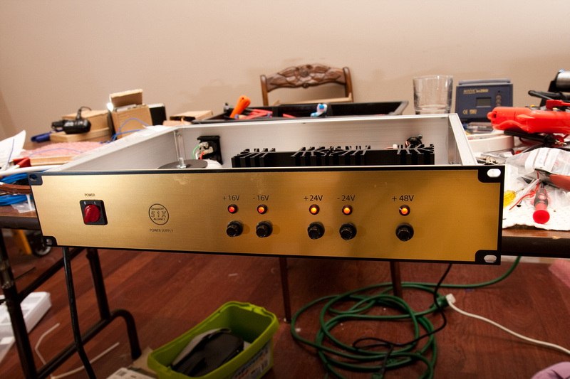
I am planning on using the 51x Floor box as a universal PSU for my racks. Each rack will have its own "universal" cable going to the PSU.  Here are a few questions:

1] Can I wire both 24V secondaries in parallel to get the extra current on the +24V rail? I dont need the -24V rail. Do I need to upgrade any component to handle the extra current?

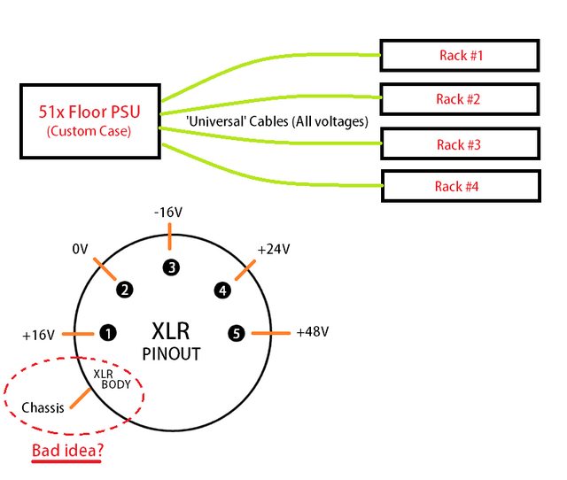
2] I would like to use 5pin XLRs because 6-Pin connectors are too expensive for me. I would have to rely on the body of the XLRs for the chassis ground. Is this a bad idea?

Maybe this helps:

EoGBA0ql.png


Thanks!
 
kante1603 said:
Hello,

have finished my floorbox today.
Did it for the "smaller jobs"( some of you might know that I´ve built a dual version before).
A breeze to build,very relaxing,high quality as always.

You "51x-Alliance-Trio"-Guys rock!

One issue:I have a left-over green LED-must I put it in the white market ;D?

O.K.,let´s get serious.
Thought I should share this:Some of us german or european builders seem to have slight difficulties with the transformer wires and their colours,which one goes where etc..
I made a little pic using the transformer description on the classic api site as a template (mea culpa Jeff!) and modified it to german colour coding.You´ll find the pdf at the end of this post.
I´m not sure if this is the same trafo Cemal sells,I got mine from Volker.Maybe someone can chime in here?

Here are some pics in detail I took from my build:


Thanks for watching,hope to have helped,

Udo ;)


I built my psu box and wired it accordingly to this post. When i power it up my main fuse blows straight away. What gets me a bit confused is that on the transformer there's two pairs of primary wires, both white/yellow that goes to the ac selector.
Any thoughts?


Uploaded with ImageShack.us
 
manglaren said:
ok, i solved the problem, wrong wiring of the primary wires. everything is functioning as it should. thumbs up!
Hello,

glad you got it solved.
Sadly my notifications didn't work for a while,sorry.

From your picture I guess ypu use the rondo-mueller transformer from Volker,right?
If so then yes,since the primary pairs have the same colour coding one might swap the leads from the first and second primary.A look at the schematics helps.In general the switch connects the both primaries in series when in 230vac mode while it parallels them for 115vac use with respect to their starts and ends of winding.

Was that the issue?
Please tell us so others get this information too.
It's also a bit easier for others when you change your profile stating your location.

Have fun,

best regards,

Udo.
 
kante1603 said:
manglaren said:
ok, i solved the problem, wrong wiring of the primary wires. everything is functioning as it should. thumbs up!
Hello,

glad you got it solved.
Sadly my notifications didn't work for a while,sorry.

From your picture I guess ypu use the rondo-mueller transformer from Volker,right?
If so then yes,since the primary pairs have the same colour coding one might swap the leads from the first and second primary.A look at the schematics helps.In general the switch connects the both primaries in series when in 230vac mode while it parallels them for 115vac use with respect to their starts and ends of winding.

Was that the issue?
Please tell us so others get this information too.
It's also a bit easier for others when you change your profile stating your location.

Have fun,

best regards,

Udo.

Thanks. Yes, it's the volker trans, and the problem you stated was the issue.
 
This post isn't directly about the floor box psu, but more about the whole 51x PSU.   

Folks, before you decide which version you're going to buy (VPR or 51x) Take an inventory of whichever modules you currently have or will want in the future.  If none of your (intended) modules use the 24V rail, DON'T BUY THE 51X version.  Buy the VPR version.   

about 2 years ago, I built two of the 51x Rack PSUs and 2 chassis.    I should've been able to power 2 chassis from each PSU, right?    WRONG.  The back panel is only drilled for one XLR, which connected to ONE rack.  It's a design flaw. the way they sell the chassis such that you're not getting what is being advertised.  "11 slots @16V and 11 slots @24V"  Well, sure that would be true if a) the case were drilled to allow two cables to connect and b) you didn't run both sets of rails over a single cable  ::)  derp derp!!!  Lesson Learned. 

About a week ago, I ordered the VPR Toroid from jeff and replaced the 51x Toroid in one PSU, and drilled a 2nd XLR jack into the rear panel.  I wired up each XLR so that only 5 pins were being used instead of 7.  Chassis 1 got the original +/-16V rails on pins 3&4 of the cable.  Chassis 2 got the old +/-24V rails now running at +/-16V on pins 3&4 of their *separate* cable, instead of 6&7.  Voila!  Two chassis powered by a single PSU and a SINGLE TOROID. 

So, before you click the "buy" button on the GDIY 51X version of this PSU, Make a list of which modules you have or will want.  If none of them will (or need) to use the 24V rail, DON'T BUY IT.  Buy the VPR version, and be able to run TWO chassis from one PSU/Toroid. 

I now have a spare PSU that I can power a 3rd chassis with for my 4 modules that use the 24V rail (G9 51x, F76).  All of my other modules in the two chassis can live happily ever after, being powered by the single PSU and without fear of being fried by that 24V rail if they get inserted incorrectly :)  And actually, if I wanted to, I could drill out the back of this other PSU and wire it up for 2 XLR-5's.  Then i'd ACTUALLY have a PSU that would power a chassis of 11 modules @16V and a 2nd chassis of 11 modules @ 24V!!!
 
Hi friends, I have an unusual problem with my 51x PSU, and I hope you can lend some insight.

I built it many months ago. Last night I switched it on to test the voltages and ALL the voltages are way too high.

My 24v rail was up around 33v. My 48v was at 65v, etc.
Naturally I adjusted the trimmers anti-clockwise and watched the voltage drop on my meter, but eventually it bottoms out without getting down to the correct voltage.

With all rails trimmed as low as they can go, this is what I'm stuck at:

16v rails:  +18.6v, and -18.4v
24v rails:  +29.3v  and -28.8
phantom:    60.6

Measuring at the rack chassis, unloaded.

Details:
I'm using the version 1 PSU board (not floor box), and the toroid from CAPI.

I remember checking all the voltages at each fuse and being happy that everything was OK. I would guess I probably trimmed the voltages to the correct values at the time, but I have no specific memory of doing that.

I later went back and added a separate circuit to power a fan, power LEDs, and a temperature sensor to kick on the fan at high temperatures.  This separate board uses its own small EI 12v power transformer and fuse which is not connected to the 51x psu other than sharing a chassis ground. (It's otherwise floating.)

Could this somehow be causing the higher voltages?

My other possible theories are:

  •  are my DMM batteries getting low? (it was 2:30am when I was doing this, not thinking of the obvious things.)

any thoughts would be appreciated,  Matthew
 
Hi Matthew,

yes,checking your dmm first might be a good idea.
It's unlikely that all rails have issues at the same time.
Also the house voltage shouldn't influence the dc rails,you're measuring after the regulators,right?

Best,

Udo.
 
I just left a friend/customers studio in Nashville. His assistant built a PSU that was having issues with high DC voltage that would not trim down. This was only on one rail though not all 5. Turns out that none of the regulators were ever soldered in at all. He had looked at the build numerous times and never noticed. Sometimes the mind will over look the glaring obvious.
 
HA!  :D  I am just the kind of space cadet who might do such a thing.

However, these do trim down successfully by several volts. Just not down far enough...
 
For anyone interested, it was indeed the DMM battery.  Thanks Udo and Jeff for chiming in.

An hour earlier I trimmed a different JLM based PSU and that "worked."  At first I thought, "It can't be the battery because I just successfully trimmed that other PSU..."  ... or did I? With a fresh battery, the other PSU read low on all rails.  I guess that makes sense. If the DMM expects a certain voltage as a reference voltage...  it only stands to reason.  :p

Bad memory.  I should label gear with post-its, especially stuff that's "finished" but not deployed. Because most likely I trimmed the 51x PSU months ago, while the pots were easy to access, then forgot. In the wired-up case, with the board mounted to the enclosure's side wall, getting to the trimmers with a jeweler's screwdriver was um, scary. :)

Hours wasted.  But good lesson. 
 
Ok simple question but looking for conformation. I am looking to put this PSU in a rack case. I will be using a toggle switch to turn the unit on. I want two leds to light up on the front  panel when turned on. So here is what I came up with. From transformer to DPDT switch one side to make the connection the other side to turn the leds on. I would connect the top terminals together?

Thanks
 
That will burn out your LEDs with like, quickness.

The most straightforward way is to just use the pads for the LEDs on the PSU and run wires to your front panel. Just use 2 of the 5 indicator LEDs, and you have the added benefit of knowing when 2 of your rails have gone out.

Or if you want to up the number from 2 to 5 LEDs, you can use the LED indicators as intended. Like this:

p940622594-4.jpg


For safety, the DPDT should be switching both the Live and Neutral wires from the IEC, with a fuse inline. If you use the switch post transformer like you subscribed, your unit will always be "on" to some extent, with power to the toroid, draining power even when not in use.

See Chunger's PSU build for an excellent walkthrough.
 
Thats a good idea. Also can I do 7 LEDS? 5 for the power indicators and two for the power. If so should I wire them parallel or series? and which one should I double up?

Daniel
 
Also do you have a part number for those heatsinks?

Here is the idea for the front panel and the LEDS
 

Attachments

  • Screen Shot 2013-12-03 at 10.11.17 PM.png
    Screen Shot 2013-12-03 at 10.11.17 PM.png
    15.5 KB · Views: 49

Latest posts

Back
Top