etheory
Well-known member
Hi there!
I've been working on a project for a friend recently that's come far enough to share.
I was asked to build them "2-channels in a box" of a versatile pre-amplifier for recording microphone and keyboards.
Price was quite a big factor, as was portability, so it had to be simple and cheap, but still have all the fancy features.
After far far too long designing (it was an excellent exercise in learning - doing a lot of my own research, and finally purchasing the full version of EaglePCB to do the work), I came up with the first design exercise for my company "evolutionary recordings" - called for the moment the ePreamp001 (for lack of a better name).
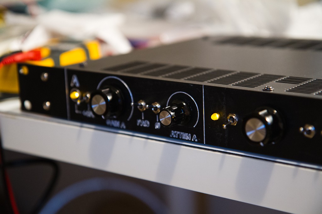
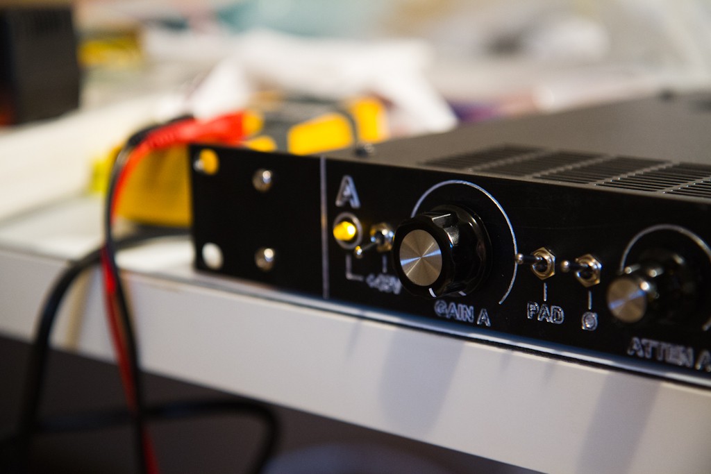
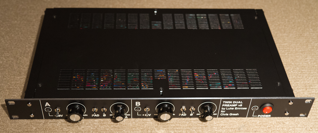
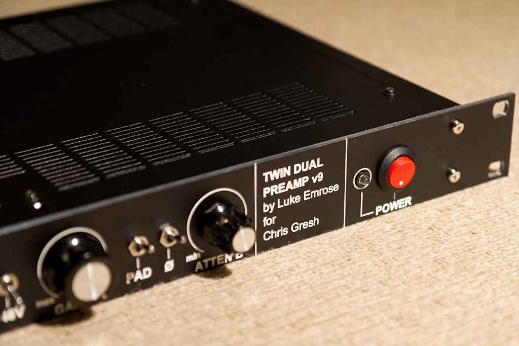
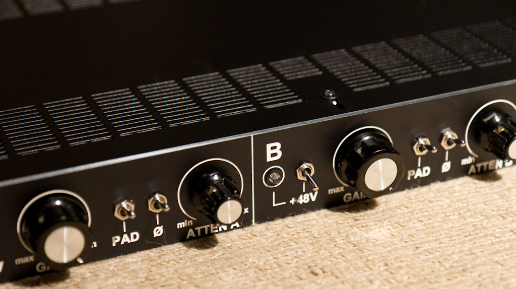
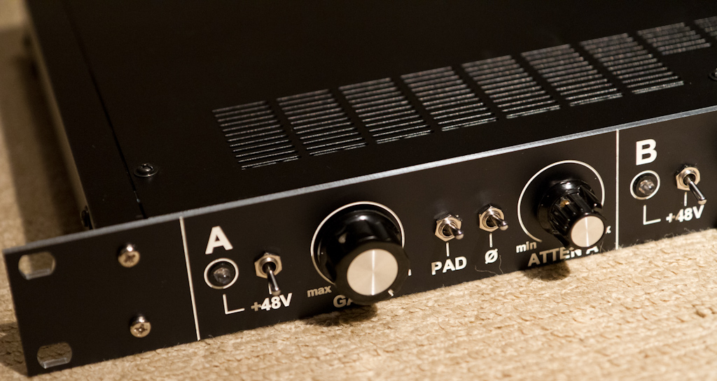
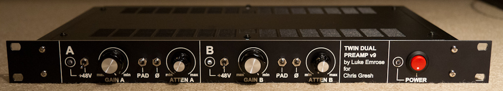
It has a 20dB input pad switch, +48V phantom, output phase reverse, a 2-stage amp with 20-70dB of variable gain and an output attenuator.
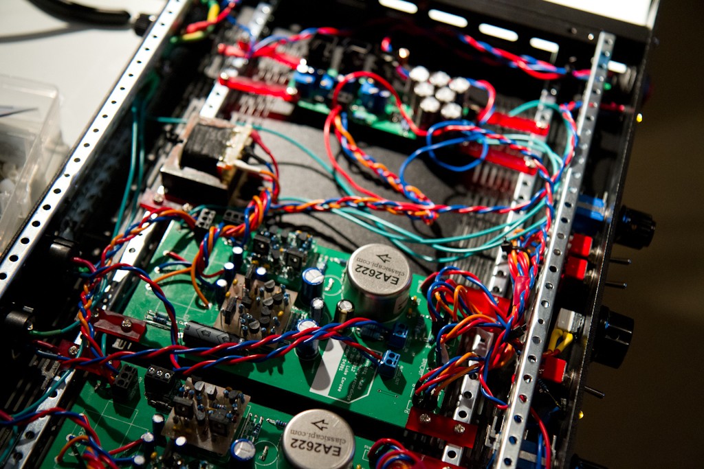
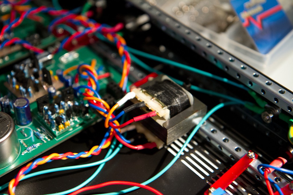
It uses the ClassicAPI 2622 input and 2623-4 output transformers.
I chose the 2623-4 mostly for it's extremely competitive price and PCB mounting ability.
I used the Tamas BigFetBloke DOA's for their extremely low cost, simple design, ability to drive a load and insane power 8) - cost was so tight here that even a 2520 or 2510 would have driven the cost up too much.
This was also my first "complex" PCB manufacturing exercise - where I decided that using a vendor to do the boards was my best bet for speed and even price (I can no longer afford 4-6hrs of manually-adjusted CNC'ing of boards - my time is worth more than that). The resulting boards worked out so well, and look and feel so amazing that I know I'll be using a professional supplier every time now - it's almost cheaper to even prototype on professional PCB's they are so cheap these days....
So having read loads of posts here, I took bits and pieces of everything I could find, simulated everything I could think of in LTSpice like a million times in a million different configurations and made something that I feel very nicely addresses the original needs of my friend.
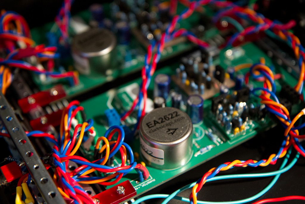
I just realized looking at these images that I maybe shouldn't have printed ClassicAPI on the board - this is NOT a ClassicAPI product, it just uses the Ed Anderson transformers - and maybe I should have written Ed Anderson on there instead - oh well - hindsight hey.... THANKS ED!!!!
So, here we go with the photos.... (please excuse the poor quality - the 7D wasn't in the house when I took these - so they were just taken on my phone).
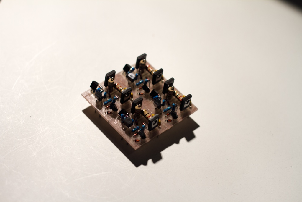
First here are the PCB's from the CNC of the BigFetBlokes (which was the process that made me realise not to CNC again - since I messed it up and had to fix stuff by soldering to the legs of other components - fun....):
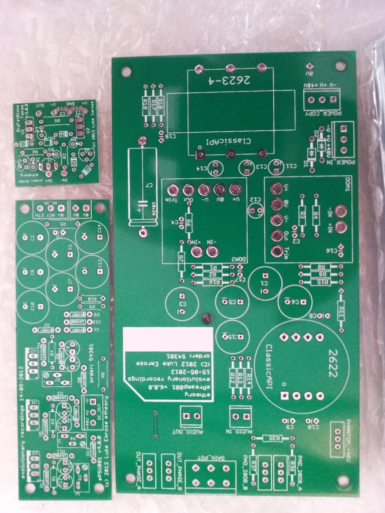
Next were the PCBs for the PSU and Preamp:
Top:
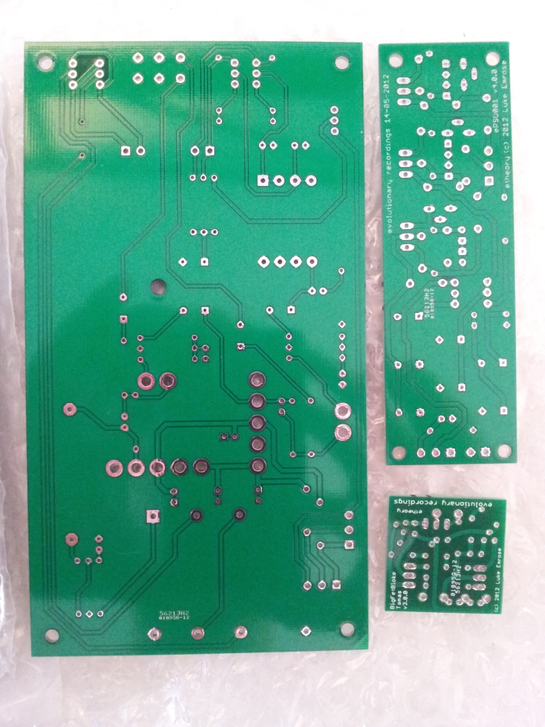
Bottom:
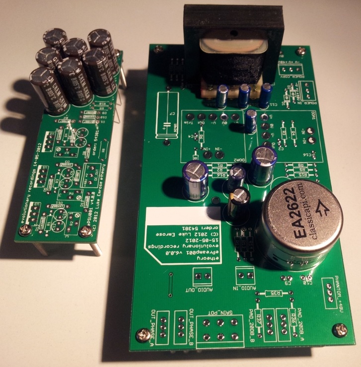
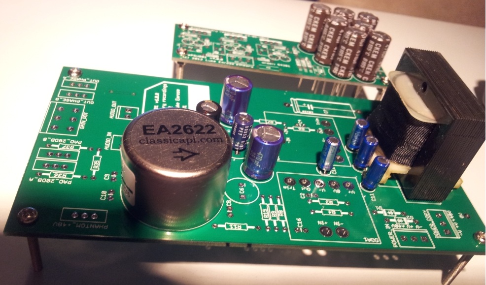
Then I did a parts test with my fingers crossed, since I had never used the EaglePCB footprints I'd made for the 2622 and 2623-4 - but as they say - measure 100 times - get someone else with more precise tools to cut once - and BOOM, everything fit perfectly:
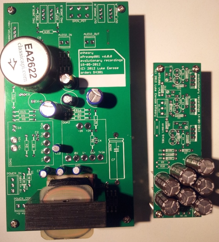
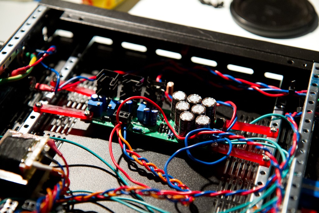
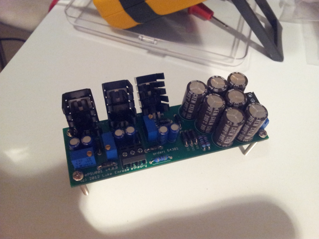
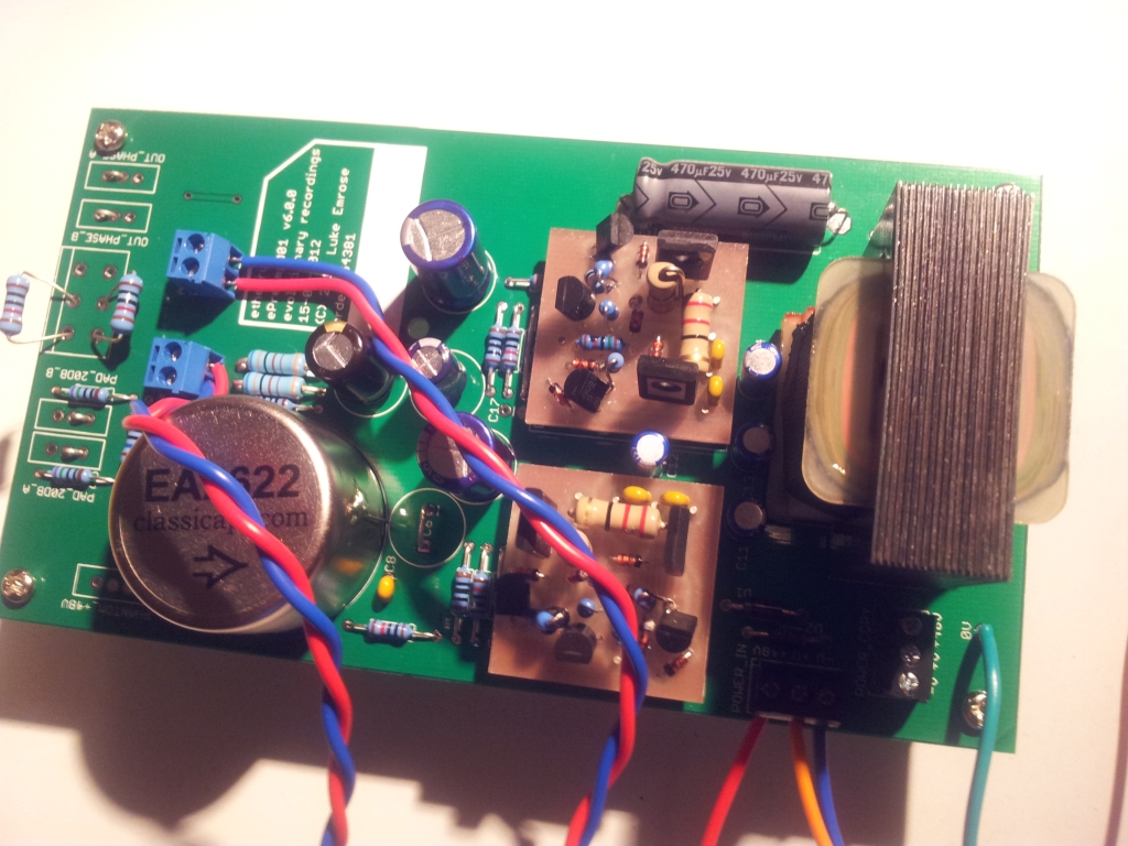
First I assembled the PSU - which worked perfectly straight off the bat (note to self, buy heatsinks that face the opposite direction 8)):
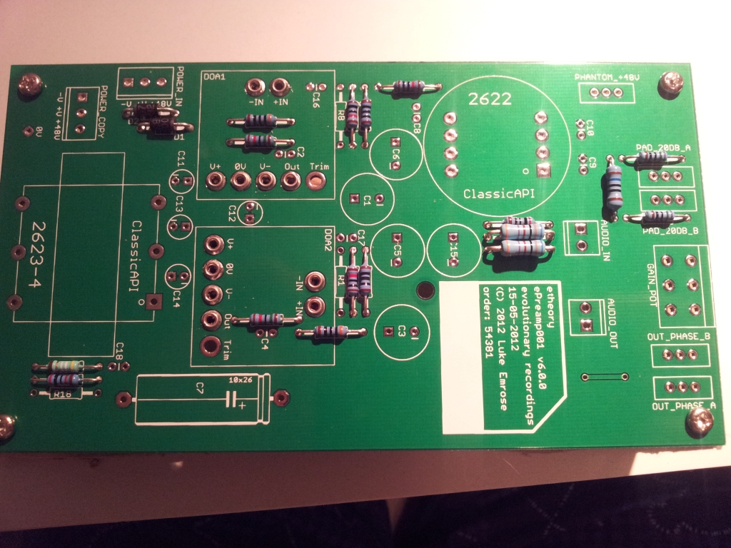
Then the preamp boards themselves - starting with the resistors:
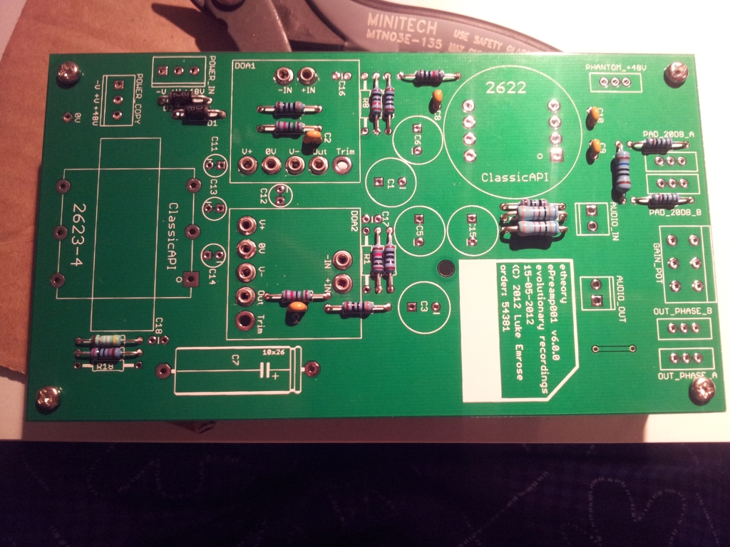
Then the small caps:
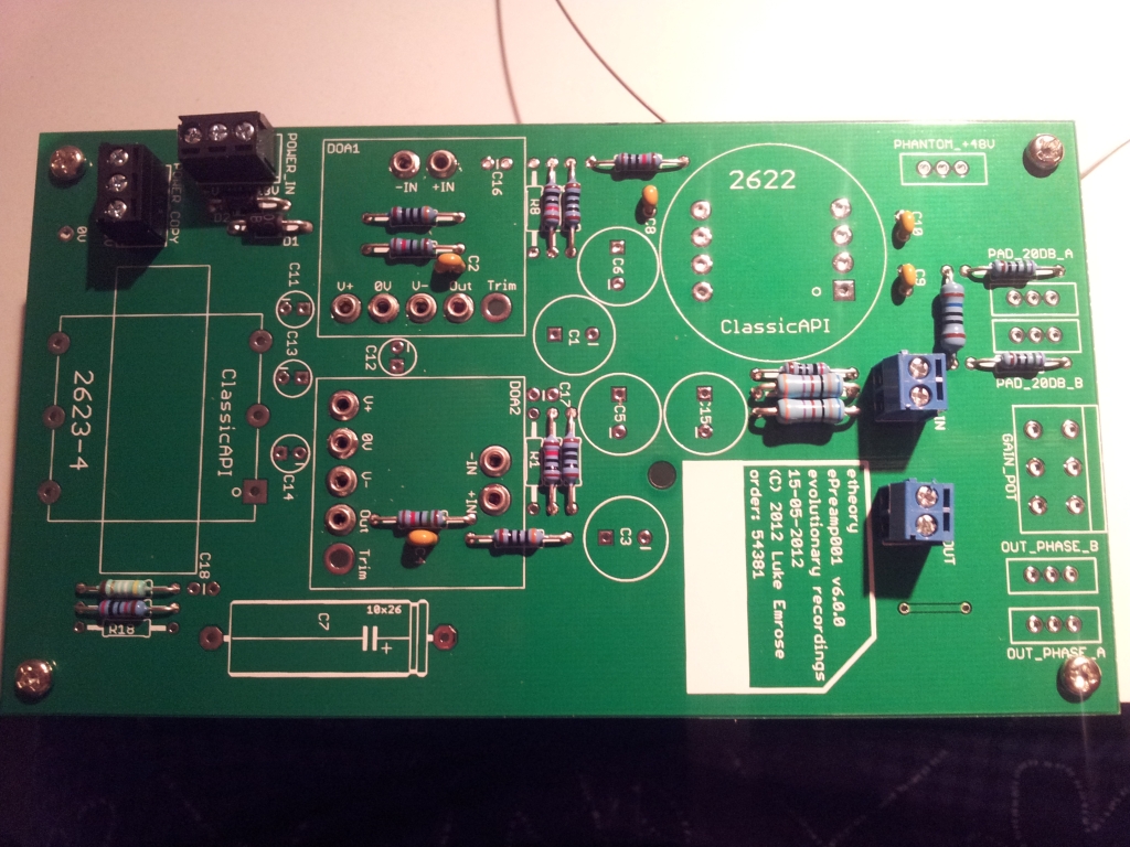
Then terminals:
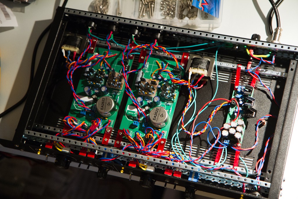
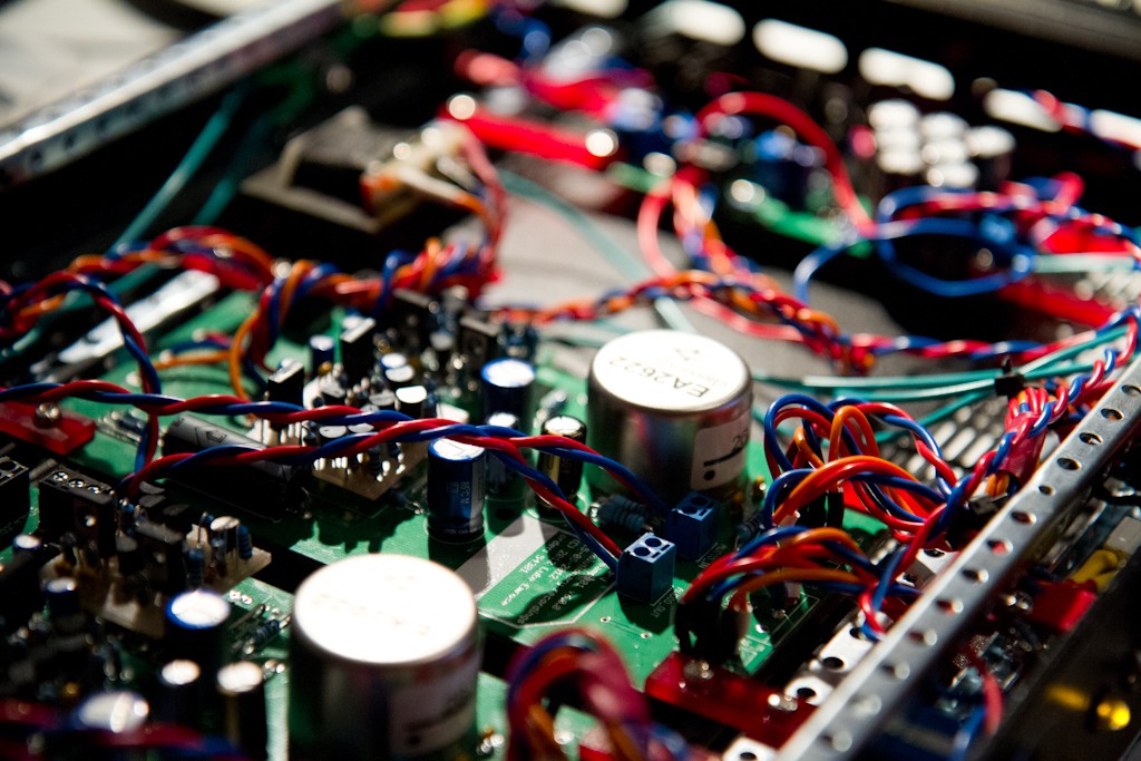
Then the big caps:
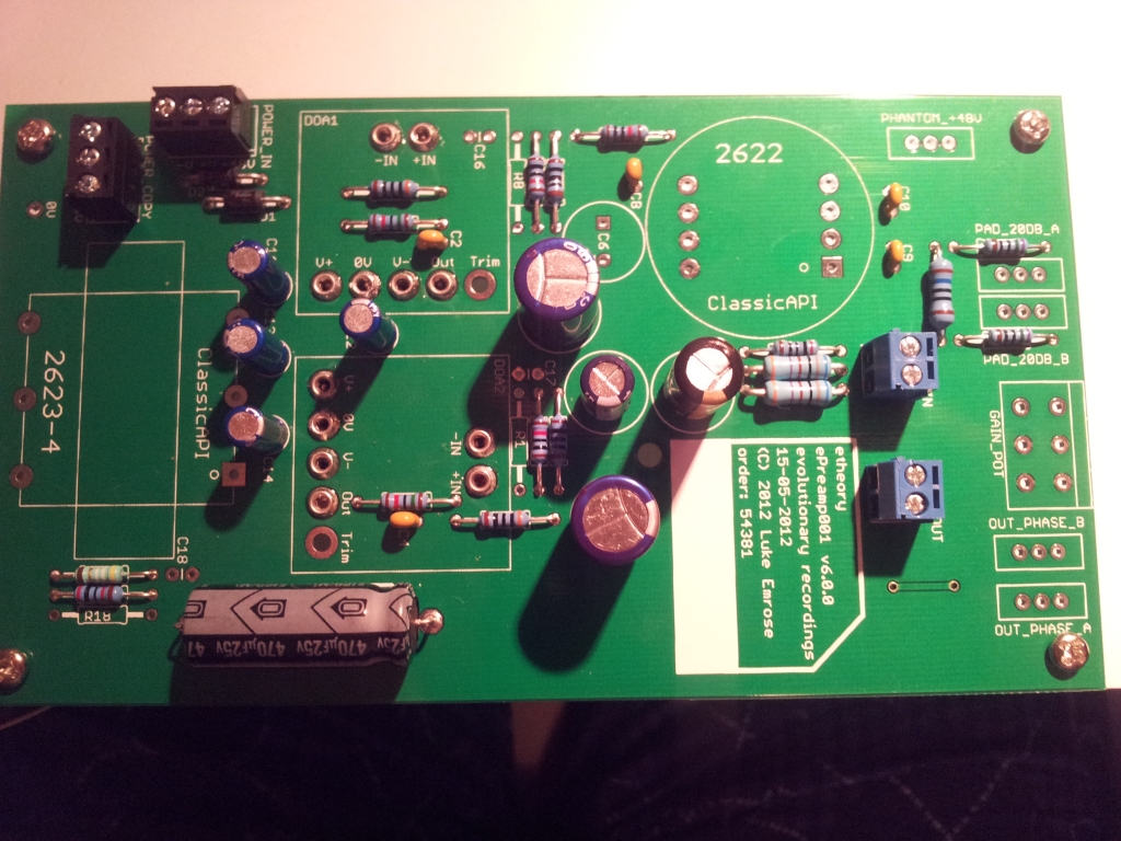
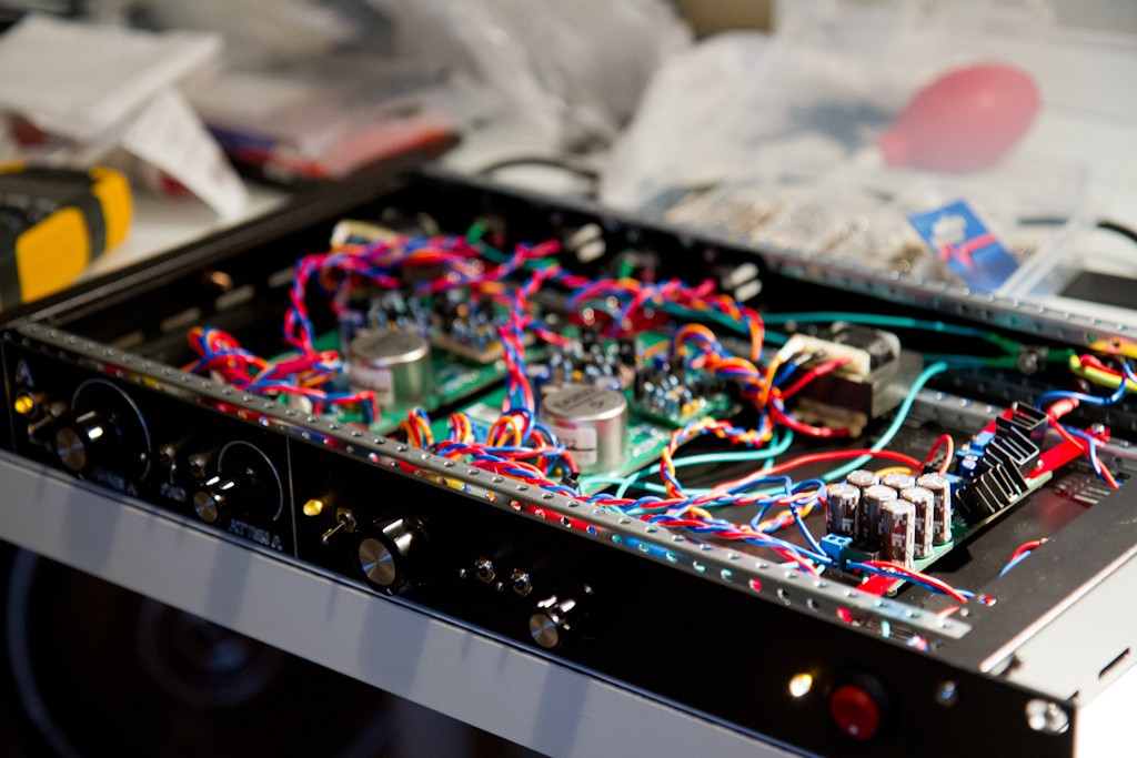
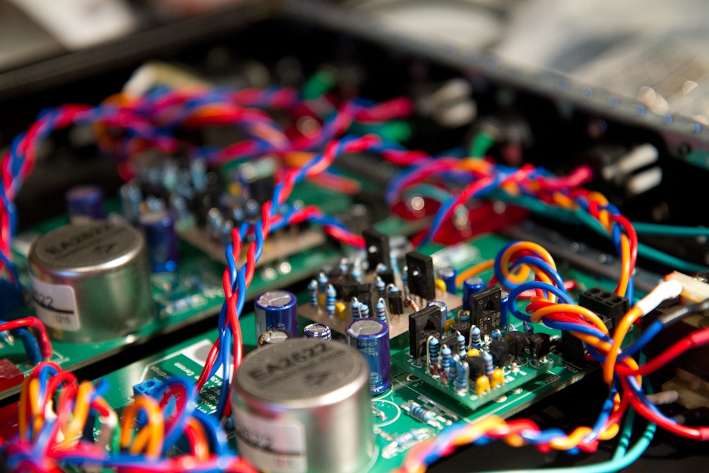
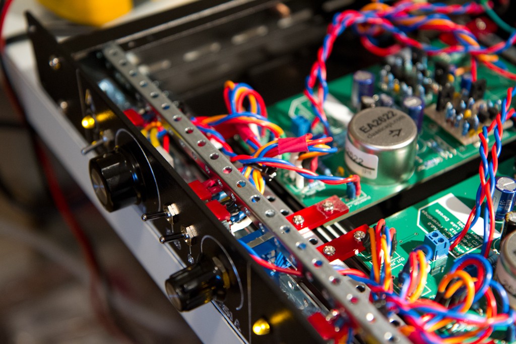
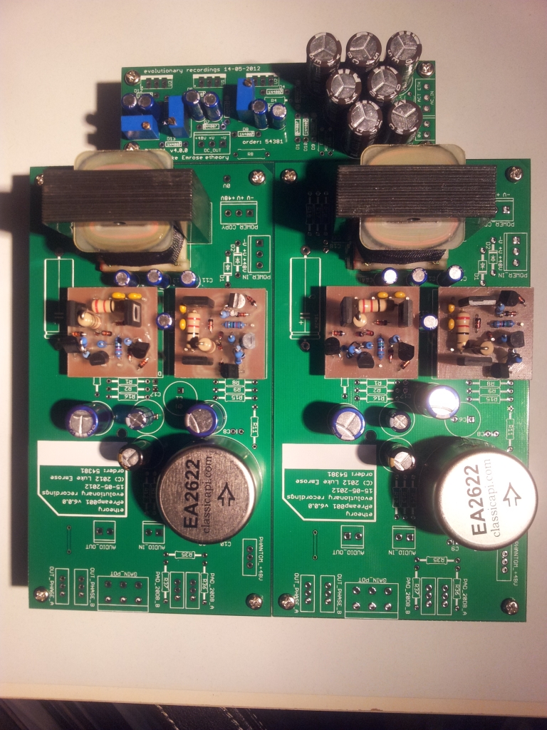
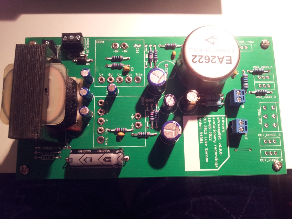
Then the transformers:
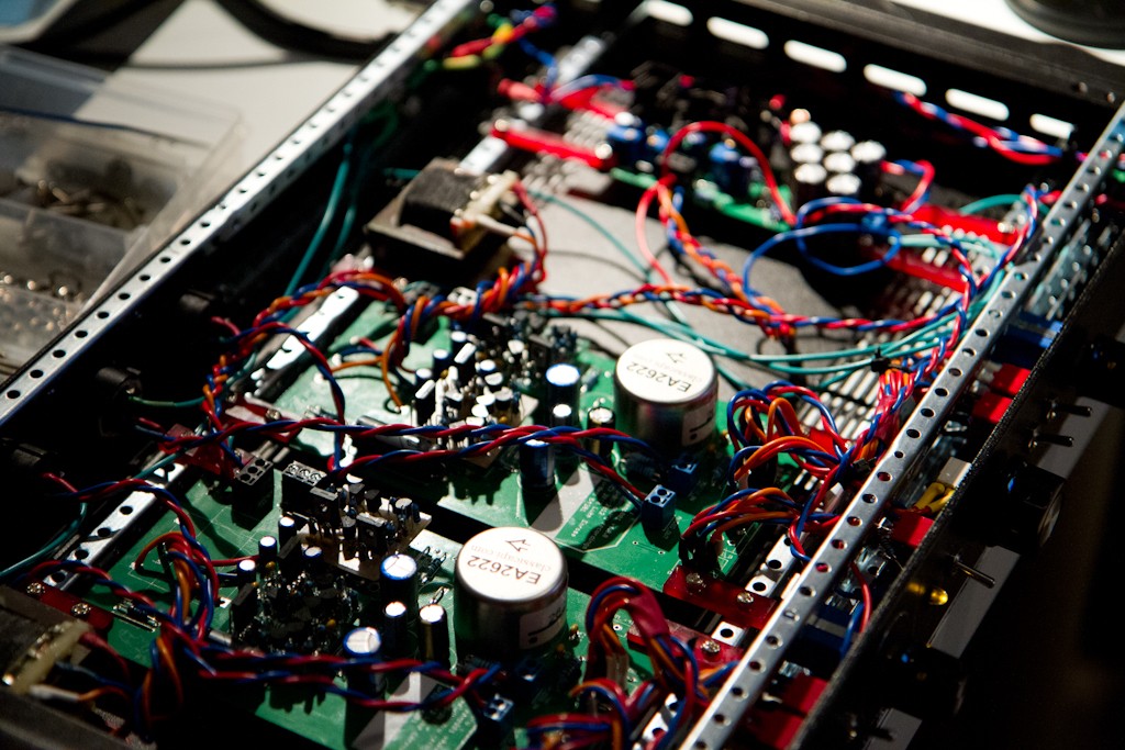
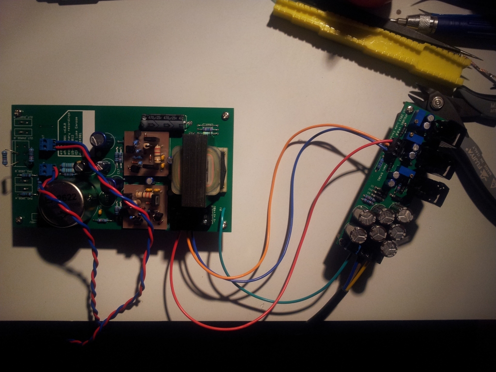
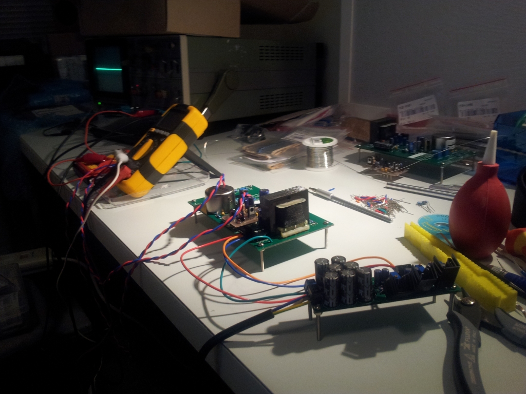
Then it was testing time:
And I am happy to report everything works just fine straight away.
There are a few things left to go, like me forgetting to buy the correct feedback and zobel caps, and then substituting with wildly incorrect values that produce a little ringing after the input transformer (1000pF instead of 220pF in the zobel with the 10K resistor, but easily fixed).
Next up I will test with all the switches and pots in place - this test was done by substituting the external parts with wire links for the switches and a 10K resistor for the pots.
Fingers crossed - I might actually have a successful preamp design here!
I couldn't be happier!
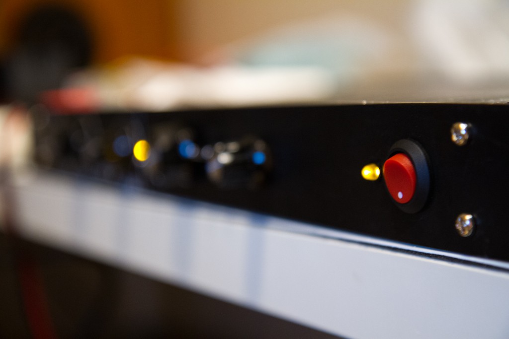
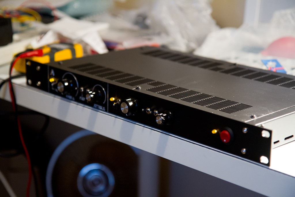
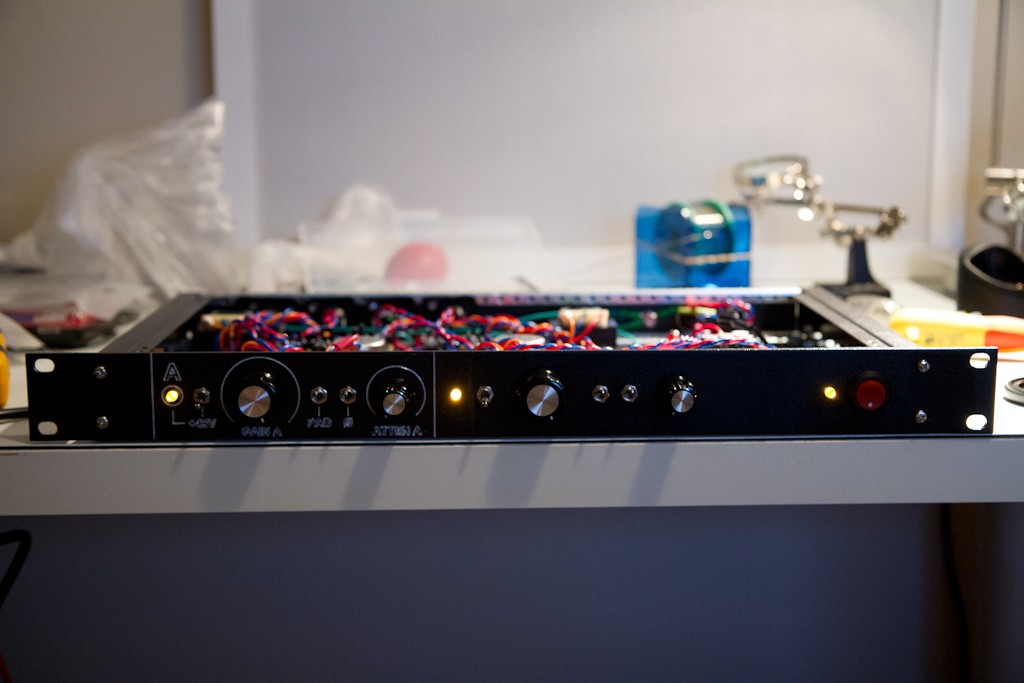
More news soon - I need about two weeks to get the rest of my organization together to finish it off and put it in a case etc. - then it goes to it's new owner for some recording!
I've been working on a project for a friend recently that's come far enough to share.
I was asked to build them "2-channels in a box" of a versatile pre-amplifier for recording microphone and keyboards.
Price was quite a big factor, as was portability, so it had to be simple and cheap, but still have all the fancy features.
After far far too long designing (it was an excellent exercise in learning - doing a lot of my own research, and finally purchasing the full version of EaglePCB to do the work), I came up with the first design exercise for my company "evolutionary recordings" - called for the moment the ePreamp001 (for lack of a better name).
It has a 20dB input pad switch, +48V phantom, output phase reverse, a 2-stage amp with 20-70dB of variable gain and an output attenuator.
It uses the ClassicAPI 2622 input and 2623-4 output transformers.
I chose the 2623-4 mostly for it's extremely competitive price and PCB mounting ability.
I used the Tamas BigFetBloke DOA's for their extremely low cost, simple design, ability to drive a load and insane power 8) - cost was so tight here that even a 2520 or 2510 would have driven the cost up too much.
This was also my first "complex" PCB manufacturing exercise - where I decided that using a vendor to do the boards was my best bet for speed and even price (I can no longer afford 4-6hrs of manually-adjusted CNC'ing of boards - my time is worth more than that). The resulting boards worked out so well, and look and feel so amazing that I know I'll be using a professional supplier every time now - it's almost cheaper to even prototype on professional PCB's they are so cheap these days....
So having read loads of posts here, I took bits and pieces of everything I could find, simulated everything I could think of in LTSpice like a million times in a million different configurations and made something that I feel very nicely addresses the original needs of my friend.
I just realized looking at these images that I maybe shouldn't have printed ClassicAPI on the board - this is NOT a ClassicAPI product, it just uses the Ed Anderson transformers - and maybe I should have written Ed Anderson on there instead - oh well - hindsight hey.... THANKS ED!!!!
So, here we go with the photos.... (please excuse the poor quality - the 7D wasn't in the house when I took these - so they were just taken on my phone).
First here are the PCB's from the CNC of the BigFetBlokes (which was the process that made me realise not to CNC again - since I messed it up and had to fix stuff by soldering to the legs of other components - fun....):
Next were the PCBs for the PSU and Preamp:
Top:
Bottom:
Then I did a parts test with my fingers crossed, since I had never used the EaglePCB footprints I'd made for the 2622 and 2623-4 - but as they say - measure 100 times - get someone else with more precise tools to cut once - and BOOM, everything fit perfectly:
First I assembled the PSU - which worked perfectly straight off the bat (note to self, buy heatsinks that face the opposite direction 8)):
Then the preamp boards themselves - starting with the resistors:
Then the small caps:
Then terminals:
Then the big caps:
Then the transformers:
Then it was testing time:
And I am happy to report everything works just fine straight away.
There are a few things left to go, like me forgetting to buy the correct feedback and zobel caps, and then substituting with wildly incorrect values that produce a little ringing after the input transformer (1000pF instead of 220pF in the zobel with the 10K resistor, but easily fixed).
Next up I will test with all the switches and pots in place - this test was done by substituting the external parts with wire links for the switches and a 10K resistor for the pots.
Fingers crossed - I might actually have a successful preamp design here!
I couldn't be happier!
More news soon - I need about two weeks to get the rest of my organization together to finish it off and put it in a case etc. - then it goes to it's new owner for some recording!
") Wouldnt mind some more color in the preamp arsenal.
Wouldnt mind some more color in the preamp arsenal.