Neumann U47FET Clone: D-U47 FET Microphone Project PCB Build thread

GroupDIY Audio Forum

Help Support GroupDIY Audio Forum:

This site may earn a commission from merchant affiliate links, including eBay, Amazon, and others.
Thanks for trying with me.
I did not miss r16, I had to rewire it from the other side because I tried too much/too hard to find out what went wrong. Project n2 got everything in place.
The  floating connection have been checked and re-checked on both projects.
And I did clean almost everytime.
But obviously, I do something wrong.
I’m in France.
 
Did you use everything from the BOM?
I Used first  the bc212 at my build, as on the original schematic,
They don’t work. So I take the 550/560 from the BOM.
What happen, when you install a capsule.
Did you check the voltages as shown on the schematic ?
 
deveng said:
it looks like you're injecting a large signal. 
:eek:  :-[
Thank a lot Jeff. I was hitting that poor thing as hard as I can. Shame on me.
Of course,  it now looks like it is working.  :-[  ::)  ;D
I do have work / tests to do to find out if everything is fine but it seems way better.
 
boomfred,

Next thing to do is use some isopropyl alcohol and clean the solder flux off the pcb.  Make sure its very clean as any flux on a high impedance circuit can mess with your signal!

Regards,
Jeff
 
So, tests have been run, and everything works perfectly.

My advice : don't try to build this mic while you are trying to repair an Acoustic 126. Levels don't match.  ;)
Did I mention how dumb I am ?

TillM said:
Did you use everything from the BOM?
I Used first  the bc212 at my build, as on the original schematic,
They don’t work. So I take the 550/560 from the BOM.
What happen, when you install a capsule.
Did you check the voltages as shown on the schematic ?
I did stick to the BOM, and of course voltages were perfectly fine.
 
index.php


how did you make the edges around the transformer? pieces of wood ? and is it black tape?

Thanks,
Baba
 
To use the additional pad :
Do I have to put the 220M R but not in the R+No Hole or use 200 + 20 R ?
 
Hello there !

To use the additional pad :
Do I have to put the 220M R but not in the R+No Hole or use 200 + 20 R ?

babaorum : from what i've understood,  if you have a 220M resistor, just put it like the picture above, with an end into the No R+ hole.
if you don't , and if you have a 200M + 20M resistors then just put them in R2 and R2+ (and nothing in the No R+ hole).


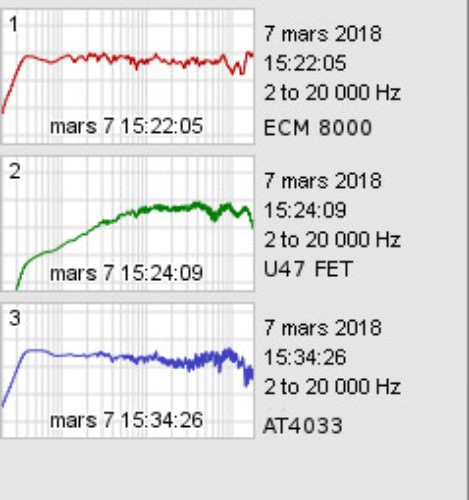
I just finished mine, it has a clean sound (no hum) , output level is ok,  but it has no bass at all. It starts to cut below 300/400Hz.
the attached image is a pink noise sent to my monitors (to the right) , and recorded with the U47 FET (to the left) ...
could it be the styroflex ?

(edit : can't upload the image, error message saying the upload folder is full)

Thanks in advance...
 
Ok Thanks, sorry the pad (attenuation) has no link with the R 220  ;D

I'm on the last stage of the project, Ihave a little question about the GND hole on the pcb , when we have the T49 transformer we don't need to have this one isn't it ? So we connect the XLR only to the 1-2-3 and leave the GND empty Am I right ?

Baba
 
Hello again,
i still have a problem on mine : clean sound but no bass at all.
i checked my solders , component orientation... nothing strange.
i tested with a spare RK12 type capsule, same thing.
so it's not my RK47, the problem comes from the circuit.

i compared the U47 fet with another DIY mic i built (with RK47 capsule),  ECM8000, and AT4033.
if you look at the result, you'll see why i think there's a big problem on my built :
ZFpoxiK.jpg


does anyone have a clue ?
 
alx said:
Hello again,
i still have a problem on mine : clean sound but no bass at all.
i checked my solders , component orientation... nothing strange.
i tested with a spare RK12 type capsule, same thing.
so it's not my RK47, the problem comes from the circuit.

i compared the U47 fet with another DIY mic i built (with RK47 capsule),  ECM8000, and AT4033.
if you look at the result, you'll see why i think there's a big problem on my built :
ZFpoxiK.jpg


does anyone have a clue ?

Did you used all original parts values? Is your build with switchable HPF? If not - check did you didn't do a fixed HPF by mistake.
Another thing which comes to mind - transformer wiring??
 
Thanks a lot for your reply ln76d !
yes i used original values. (i used the mouser BOM of this topic) 
my built is like the one on this topic, so it has a jumper for the Low Cut,
but i didn't put the jumper.
but I thought about that too, so i tested that the LC was not engaged without the jumper.
(anyway it starts to cut LF  around 300/400 Hz, so that would be a huge Low Cut.)

for the transformer (AMI T49),  i'm going to check that again...
(if i recall , when i read the topic, there was 2 different answers about how to wire it, so maybe i picked the wrong one ! :) )

thanks again !
 
stupid question :
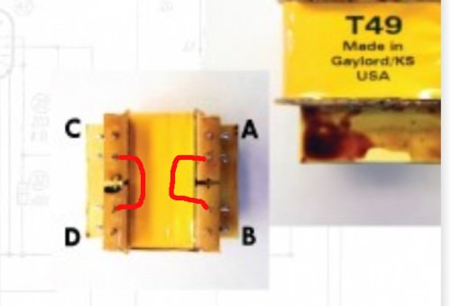
on the T49, you need to connect the inside pins of A-B and of C-D like that ?
YTQN8Ga.jpg
 
so my T49 seems to be correctly wired :
1 (rt) : A
2 (br) : B
3 (vi) : D (xlr pin 3)
4 (bl) : C (xlr pin2)

i asked the stupid  question above because on the pcb, the 1(rt) and 2(br) are connected together (continuity test) when the inside pins of the transformer are connected. it doesn't seem normal to me (but maybe i'm wrong)
1(rt) and 2(br) on the pcb are not connected together when i disconnect the inside pins of the T49, but in that case, no sound (or very weak ) is coming out the microphone except "wind"...

so, are the 1(rt) and 2(br) are supposed to be connected together ?
if not, the T49 has a problem, right ?
 
For the colors,  i didn't check the schematic or anything it's related to.
Isn't t49 exactly symetric - is there no possibility to connect it opposite? Or are there markings a/b/c/d?
I rather doubt that there's something wrong with transformer, untill you didn't overheat connector pins and loosed internaal connection.
If you are not sure transformer proper orientation then measure resistance A/B should be higher than C/D.
 
thanks again ln76d,
yes the a/b/c/d are written directly on the T49.
T49SpecSheet.jpg


i checked the resistance :
A/B = 15 ohm (so i guess my multimeter thinks it's like continuity)
C/D=675 ohm
it's the opposite of the values i read in this topic !  :eek:
 
ok, so i "reversed" the connections on the T49 (A/B =xlr 2/3, and C/D=pcb 1/2) and...
plenty of bass ! beautiful sound !

so the folks at AMI put a sticker on the T49 to mark the A/B C/D, but they put it the wrong way ! (on mine)  :mad:
i would have preferred no sticker at all...
but i'm dumb, i measured the resistance of A/B C/D but did not noticed they were reversed ...

anyway, i'm happy now..
thanks a lot  ln76d for pointing the right direction !
(and thanks to poctop for this great mic, now i want another one !)
 
Hello, I got my PCB's the other day, they are lovely looking. I've ordered pretty much everything but I'm not sure what XLR type to get to fit my SCT700/GT-2B unit? Any help on that front?
 
Hello there,
I picked that : https://www.mouser.fr/ProductDetail/502-QG3M
The one on the right.
502-QG3FD.jpg
 
boomfred said:
Hello there,
I picked that : https://www.mouser.fr/ProductDetail/502-QG3M
The one on the right.
502-QG3FD.jpg

Thanks mate, typically, I'd just placed my order for the BOM, but I've managed to get Mouser to add this on. Appreciate the help :)
 

Latest posts

Back
Top