El Toro - Yet Another Discrete Op Amp

GroupDIY Audio Forum

Help Support GroupDIY Audio Forum:

This site may earn a commission from merchant affiliate links, including eBay, Amazon, and others.

Matador

Well-known member
Joined
Feb 25, 2011
Messages
3,091
Location
Bay Area, California
Here's something I've been toying with.  I was interested in DOA designs, and read all of Doug Self's stuff along with a ton of great information here at GDIY (a special thanks to PRR and Sam G. for all of the great write-ups here). 

So here it is:

eltoro_schematic.jpg


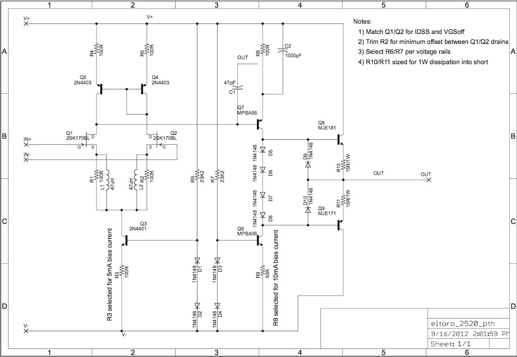
So it's essentially the front end of a JE990, converted to JFET devices for the differential pair glued to a standard VAS and follower output topology, all in a regular 2520 standard format.  I added two additional diodes in case I want to experiment with Darlington type output devices.  I assume I'll be able to bridge across two of them with the devices I plan to use (the MJE171/181 pair).

Here is the open-loop simulated response.  I was shooting for about 90-ish db of gain open loop, as I was planning on using these in a twin-servo type topology where each devices runs at 35-40dB max each.

eltoro_openloopgain.jpg


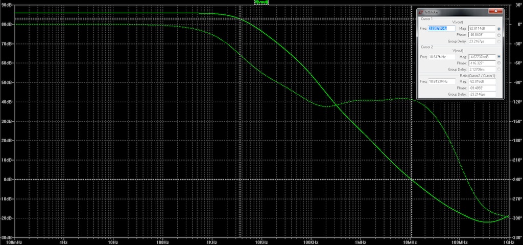
Open-loop gain falls to unity at about 10MHz.  The plot seems to indicate a zero in the 5MHz range which i'll have to investigate further.

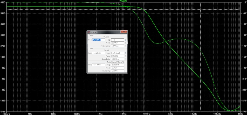
Here is the closed loop gain with the op-amp wired in the non-inverting follower configuration.  The feedback resistance is 10K with 47pF of phase-lead compensation.  This is driving into a 600 ohm load:

eltoro_6dbgain.jpg


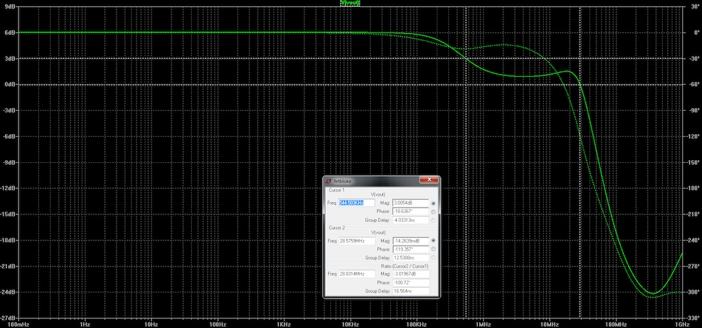
There is a peak in gain at about 20MHz:  I'm assuming this is an interaction between the bypass inductors in the front end and the gate to source capacitance of the JFET's.  Perhaps I need to lower the dominant pole a bit more by increasing the Miller capacitor?  Phase margin looks good at about 60 degrees.

Here is the plot showing 40dB of gain:  phase margin is 70 degrees.

eltoro_40dbgain.jpg


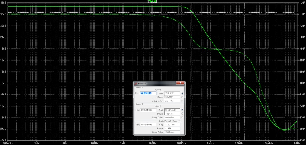
Lastly here is a plot showing 60dB of gain, with about 50 degrees of phase margin:

eltoro_60dbgain.jpg


Slew rate into a light capacitive load is about 20V/us.

Based on the simulation, I feel that the op-amp might be under compensated.  Open loop gain does not begin to fall until after 1KHz, however there appears to be enough phase margin with the existing compensation values.  However this will change as the load becomes more capacitive.  Slew rate seems pretty fast but I don't have a good feel for what denotes "fast enough".

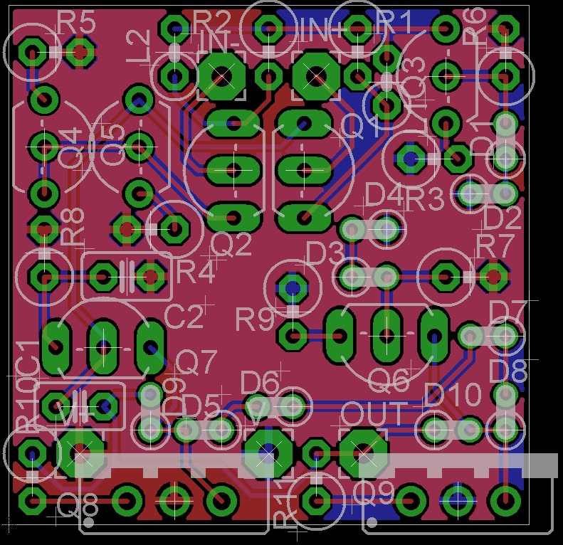
So here is the layout in a standard 2520 format:

eltoro_layout.jpg


Any criticism or feedback is appreciated!
 
A comment and a plea.

Comment: I wondered of the zero at 5MHz has anything to do with the 47uH inductors in the first stage.

Plea: There are very many DOA designs for audio but they all seem to try to emulate an integrated op amp. In particular a large open loop gain is coupled with a rather low dominant pole to ensure stability and low distortion over a wide range of closed loop gains. Whilst this simplifies the design process for the end user it has (at least) two problems for audio applications.

First as you have noted the phase margin varies with closed loop gain - not surprising since the open loop gain is fixed and gain is altered by changing the amount of NFB. Second, the pole well within the audio band means that distortion rises with frequency for any gain since the closed loop gain drops with frequency and distortion rises with gain.

I am not going to make any comment about what these mean in terms of the sound but suffice to say I think both should be avoided for audio applications.

A solution is first to move the dominant pole above the audio band. That way, no matter what the gain, the NFB is effective at reducing distortion across the entire audio band. This makes stability more difficult but only if we have a huge open loop gain and lots of NFB. So the second part of the solution to vary the open loop gain as part of the NFB gain setting mechanism in such a way that the amount of NFB is practically constant so there is only one case for which we need to ensure stability. The third and final part of the solution is to reduce the open loop gain and redesign the signal amplifier very low open loop distortion. This meanswe need less NFB for a given distortion and lower open loop gain eases stability.

Exactly how the above is achieved I have no idea but I would  love to see it investigated. I know the early Neve DOAs embodied some of these principles, specifically having the dominant pole above the audio band but that resulted in a minimum gain below which the amp was not stable. I try to use the same principles in my tube preamp designs mainly because very high open  loop gains are just not possible with tubes but I see no reason why they would not benefit a DOA design.

Cheers

Ian
 
I know what the chokes do in the 990.

I don't know what they do here. Seems like almost-nothing. Sim it open-loop with and without.
_______________________________________________

> move the dominant pole above the audio band

In general: we can't increase the unity-cross point (it is already as high as we can manage).

So to "move the dominant pole" we can only reduce the DC gain, and increase closed-loop THD in the audio band.

> the second part of the solution to vary the open loop gain as part of the NFB gain setting mechanism

Yes, that does work very well, but not with ordinary general-purpose (voltage feedback) op-amp designs such as are found throughout audio. Current-feedback _is_ common a few places, most notably in most transformerless balanced mike inputs.
 
Are you approaching this with any kind of plan or design theory?

Do you know why Deane put the inductors in his input LTP in the first place?

Hint... input stage transconductance matters for high slew rate and stability margin. (another popular way to reduce input stage transconductance is to increase LTP emitter degeneration resistance, but those add noise and DC errors.)

My suspicion is that the inductors are not doing much constructive with JFET input devices due to their lower transconductance than bipolar devices. You might want to try with them removed completely. 

JR
 
JohnRoberts said:
Are you approaching this with any kind of plan or design theory?

Do you know why Deane put the inductors in his input LTP in the first place?

Hint... input stage transconductance matters for high slew rate and stability margin. (another popular way to reduce input stage transconductance is to increase LTP emitter degeneration resistance, but those add noise and DC errors.)

My suspicion is that the inductors are not doing much constructive with JFET input devices due to their lower transconductance than bipolar devices. You might want to try with them removed completely. 

JR

I have several BJT based DOA's that seem to work well:  I wanted to try and adapt a proven topology to use a FET input.  I was hoping this would reduce the need for input bias compensation and save some parts count from my board if possible, and to give another color in the crayon box.  Plus, these types of things force me to read up and study areas that have gone ... rusty ... over the years. ;)

I assumed that the inductors increased the effect of emitter degeneration as frequency increased:  a way of limiting open-loop gain by inserting a pole somewhere above the audio band.  I figured the indention was to limit the interaction within the pass band (e.g. audio) but get the stability benefits (regarding tendencies to oscillate above the audio band).

Is this incorrect?
 
http://users.ece.gatech.edu/mleach/papers/InputStage.pdf

This is a good starting point... more later..but JFETS don't need as much attention to deliver clean high slew rates.

JR

[edit] ok, I realize that doesn't really answer your question...

To your point about reduced input bias current, yes JFET inputs will be dramatically lower current. There is no free lunch, so for the improved input current, you get worse DC offset characteristics, in the trade.  In fact you probably want to select for Vgs to get matched parts.

These days they make some decent dual JFETs that might make a good input pair.

[/edit]
 
OK, the chokes may be doing something.... after all, they do very little in the 990.

One pole is stable. Two poles "should" be barely stable. Real amplifiers have non-dominant poles, so two poles is (according to Murphy) unconditionally UN-stable (because the 'minor' poles add-up to give more than 2.000 poles at unity cross).

What is between 1 and 2? 1.5 poles! 9dB/oct 30dB/decade. This is stable. AND it throws-away gain faster than 1-pole compensation. So we can run the DC gain further up the audio band. Ultimate phase-shift is between 90 and 180 degrees, 135 degrees, 45 deg short of howling.

How do we contrive 1.5 pole response?

It's possible: a pink-noise filter does the right thing.

Pinking filters are usually (always?) cascades of pole-zero pairs. Flat, 6dB/oct, flat. Stagger these with the right offsets and frequencies, it looks like 3dB/octave. Look close, it is bumpy. Use more pole/zero-pairs, the bumps may be reduced as far as needed. For our purposes the bumps do not have to be super-small. 40 deg phase margin won't kill us, or 110-130 deg wobbles won't lose a lot of frequency range.

In fact it appears that Jensen uses just one pole/zero pair, to throw away just 10dB of gain. Your 2SK170 have 'emitter' impedance near 40 ohms, with 100 ohms bypassed, 11dB step, no difference.

I'd have to do real thinking to see where the step comes. Not tonight.

If I have other criticism....

Trimming R2 for offset looks wrong to me. In general, you won't get the extreme match from JFETs that Deane got with the interdigitated BJT chip. What you gain from reduced bias-current is lost in stray offset? And in some circuits used *with servo*, the input offset may not be so important?

Selecting R9 for 10mA (in Q6? In Q8Q9?? Why is this not with the other notes?) seems fiddly. Q6 can run 8mA or 12mA no real difference. And dialing Q8Q9 this way probably puts Q6 at some extreme current.

Considering part prices now, D5 D8 could as well be MJE1_1 transistors, diode-strapped, so the voltage/current/temperature really tracks Q8 Q9.
 

Latest posts

Back
Top