Neumann U67 Clone : D-U67 Tube Microphone Build Thread.

GroupDIY Audio Forum

Help Support GroupDIY Audio Forum:

This site may earn a commission from merchant affiliate links, including eBay, Amazon, and others.
Awesome! Very much looking forward to the build guide, my understanding is that correct component placement is critical for the sound on this build. Going to have to make sure my wiring is extra pro on this one.

wave said:
Hello fellow builders,
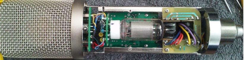
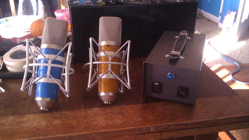
I still have to build my PSU but I wanted to let everyone know that Eric (tskguy) came by with his PSU and my AMI DU67 is ALIVE!!!!!
It works perfectly (all patterns) and sounds great except for the fact that I'm still waiting for my HK-67 capsule so I have a Chinese K-67 in there for testing that has way too mush 4-7K response.
PSU components are on the way. I'll have it built up this weekend and then I'll be able to finish up my build manual.

Great project but not the easiest one to do. It's very satisfying to have the mic work right out of the block tho.

Dave

pics and sound samples coming...
 
dmp said:
What is the calibration input used for?

It's for checking the frequency response of the amplifier. You feed a 600ohm 1K tone at -18 into it and measure the output.
The old owner's manual has the info in it.

bkbirge - it's def necessary in the HiZ section to make sure your work is nice and tidy. There's a lot of floating components and not much space up there in the AMI build (there's much more room in the ioaudio build)

Dave
 
It's for checking the frequency response of the amplifier. You feed a 600ohm 1K tone at -18 into it and measure the output.
The old owner's manual has the info in it.

Thanks - it's not for calibration as much as a test, apparently. A BNC jack would make the most sense if installing, I suppose.
I found this info in the manual for others who are interested:

"For purposes of checking the frequency response of the amplifier, a test signal may be fed to the instrument jack marked "calibrating input" at one end of the power supply. Proceed as follows: From the 600 ohm output of a signal generator, feed a 1000 cps tone at a level of -18 dbm to the calibrating input. You may use the model z-58 dummy head or can proceed with the regular head assembly plugged in. The three switches are set for "omni", full sensitivity, and linear frequency response. The following output levels are to be observed at the output of the 150/250 ohm impedance, using a vacuum tube voltmeter:

1000 cps:    -38dB    1dB
40 cps:        -43dB    1dB
1500 cps:  -48dB      1dB
 
dmp said:
It's for checking the frequency response of the amplifier. You feed a 600ohm 1K tone at -18 into it and measure the output.
The old owner's manual has the info in it.

Thanks - it's not for calibration as much as a test, apparently. A BNC jack would make the most sense if installing, I suppose.
I found this info in the manual for others who are interested:

"For purposes of checking the frequency response of the amplifier, a test signal may be fed to the instrument jack marked "calibrating input" at one end of the power supply. Proceed as follows: From the 600 ohm output of a signal generator, feed a 1000 cps tone at a level of -18 dbm to the calibrating input. You may use the model z-58 dummy head or can proceed with the regular head assembly plugged in. The three switches are set for "omni", full sensitivity, and linear frequency response. The following output levels are to be observed at the output of the 150/250 ohm impedance, using a vacuum tube voltmeter:

1000 cps:    -38dB    1dB
40 cps:        -43dB    1dB
1500 cps:  -48dB      1dB

That is correct , they remove it at some point after 1963.  here is the 1963 Manual with  info about the U67  Preamp Checkup.
Thanks Guys,
Dan, 


Attachments

  • 1963mar.pdf
    168 KB · Views: 49
i have an original power supply  NU 67 Neumann (but not the mic) ,
do you think i could use it with the D-U67 Tube Microphone ??

thanks
 
franckboxe said:
i have an original power supply  NU 67 Neumann (but not the mic) ,
do you think i could use it with the D-U67 Tube Microphone ??

thanks

Absolutely  ;)  Just make sure to check the cable configuration from the psu to the mic
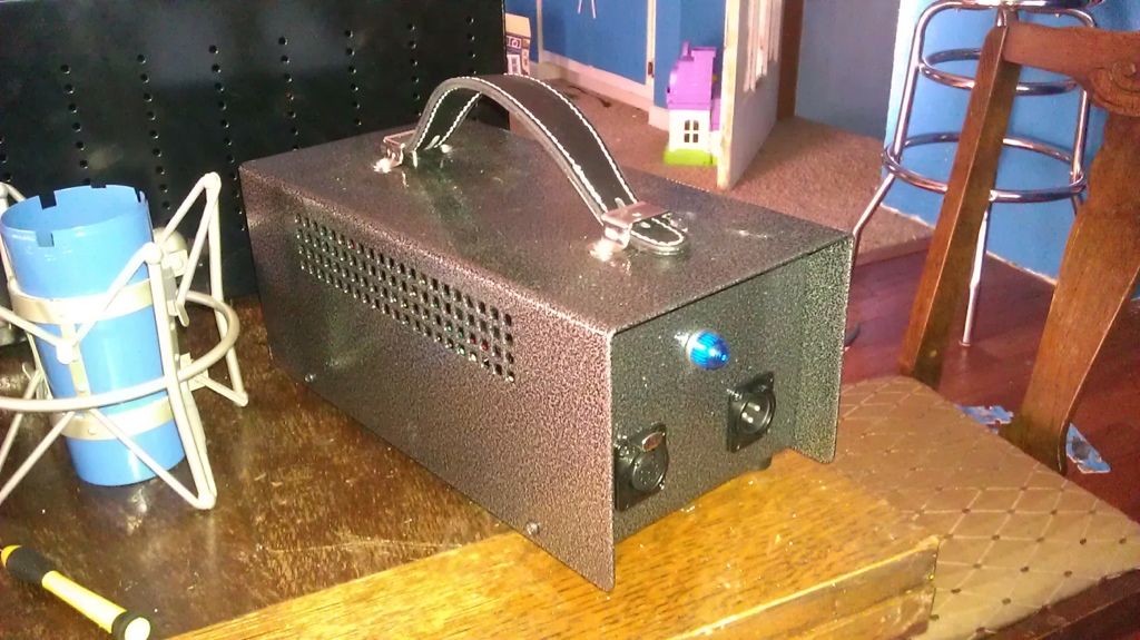
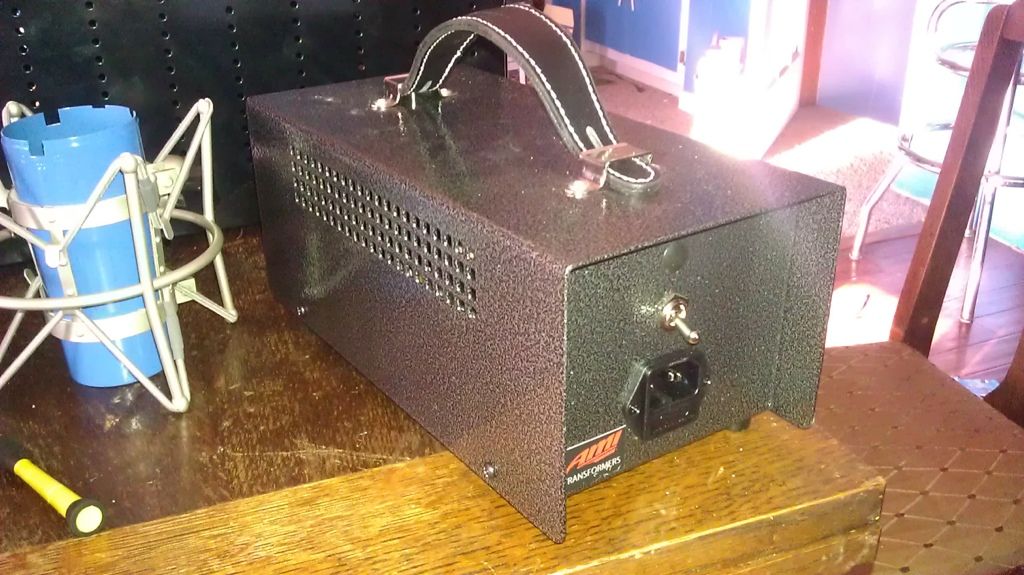
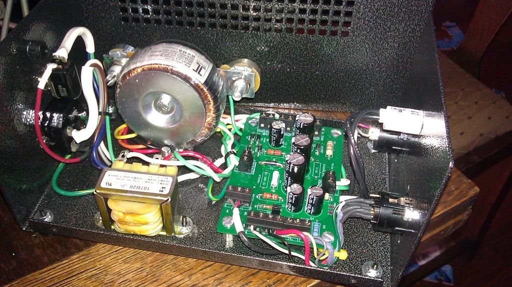
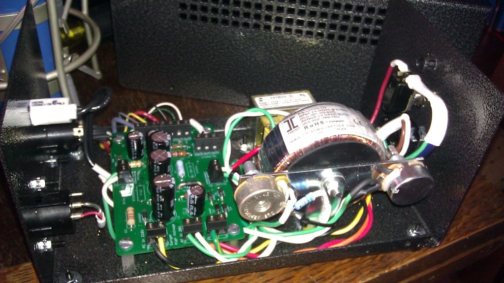
Dan,
 
Congrats to Wave for is really nice build 8) , Dave was involved at the very first stage of the developpment of the D-U67 microphone as you can see that he has etched his own adaptor board,  I was allowed to post picture of his new toy,  Keep us posted,  I do like the AMI transformer look  8)

AMIA.JPG

58d0281993933.jpg

Best,
Dan,
 
D-U67 Build Folder.zip updated. added document manual 1963 and some tube socket suggestion in the U67doc
Dan,
 
Hello peoples,
So I've got all my PSU parts. I had forgotten to add a power switch to my BOM (I'm using a custom BOM which differs slightly form the one Dany posted on page one)
SO I ran over to the shack and got one. It was only $3.20 and comes with that cool metal on/off label.

I am using the Hammond 513-0900
http://www.mouser.com/Search/ProductDetail.aspx?R=513-0900virtualkey54600000virtualkey546-513-0900

I decided to machine my own case instead of buying the collective cases PSU box because I want to use the amphenol connectors on the mic, cable, and PSU. Also because while doing the machining is a pain in the arse, I can do the layout of the components however I want, and I want to have the power transformer mounted vertically on the back panel.

So all that being said do you guys want me to include a layout template for the PSU components in the build manual?

Let me know what you think
Dave
 
Awsome Duo of Lolly-pops, Kudos  8),  congrats for the build very nice  ;) ,
Best,
Dan,
 
beware of this , it has been discussed earlier in the thread and just want to warn again everybody on this,

Important Note
The only 2 parts that is not (Europe 230V) compatible is the hammond 20VAC and the PSU pilot Lamp wich is 120V everything else is fine except the fuse will need to be 0.1A instead of a 0.2A for north America, you will need a minimun 6VA traffo for the filament side,
alternative part number are discussed in this thread here : http://www.groupdiy.com/index.php?topic=49675.20

 
wave said:
I thought I would throw up a photo of my PSU
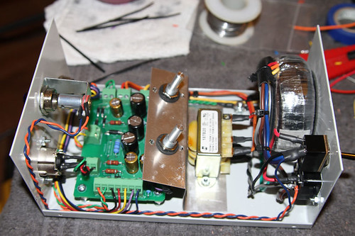


Dave

Hey Wave ,  awsomely clean build here , your are not raising the bar you are the bar ,
nice stand for the pots  8)

best,
Dan,
 

Latest posts

Back
Top