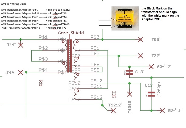
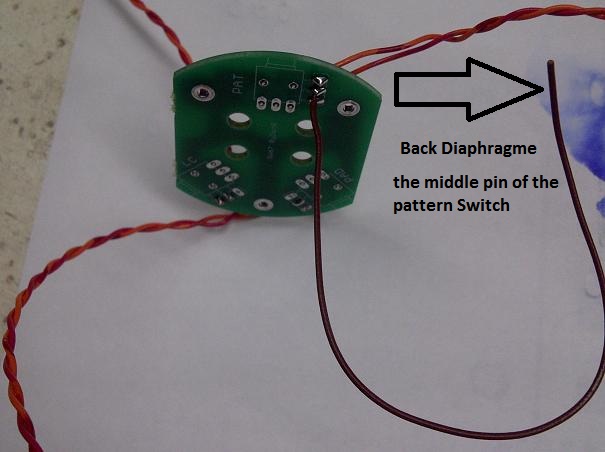
Here is the correspondance on the pcb pad for the U67 Mic pcb
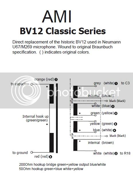
AMI sent me the updated schematic with these details below.
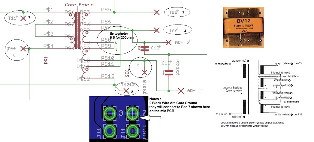
The circuit:
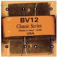
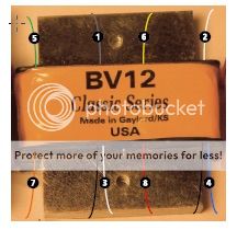
... and the reference image:
... still wondering if anyone here can tell me what the black wires connect to? Not sure what the dotted-dashed line with the "&" symbols in the circuit diagram denote.
Best,
Rich


")