You are using an out of date browser. It may not display this or other websites correctly.
You should upgrade or use an alternative browser.
You should upgrade or use an alternative browser.
REDDI DI
- Thread starter dandeurloo
- Start date


Help Support GroupDIY Audio Forum:
This site may earn a commission from merchant affiliate
links, including eBay, Amazon, and others.
Hi Ian! yes i am still breathing,
get a group buy together for about 6 so you can split up the 64 dollars for international shipping (ouch!)
these are a 1/2 lb over what we can send first class which is a real bummer.
get a group buy together for about 6 so you can split up the 64 dollars for international shipping (ouch!)
these are a 1/2 lb over what we can send first class which is a real bummer.
no problem, that's a great solution!
Should be fine like any ac heater @ 6.3V
No sound clips anyone? ??? :")
What choices has anyone made with regard to where the pot goes in the topology?
Where does @DanDeurloo put his in the ZOD DI?
No sound clips anyone? ??? :
What choices has anyone made with regard to where the pot goes in the topology?
Where does @DanDeurloo put his in the ZOD DI?
I made mine with AC heaters. I have some hum issues but think they're related to the proximity of the power transformer.mp5hkm said:any reason i couldn’t power the heater using a 6.3v tap instead of converting it to DC?
I'll continue tweaking it when i have some spare time.
Rob Flinn
Well-known member
I built this with a.c heater & am not experiencing any hum issues. Just keep the works away from the Power transformer & follow normal grounding rules.
Finally got around to building this guy. It sounds absolutely wonderful and has NO noise whatsoever but the 47uf capacitor after the bridge is getting pretty hot. (doesnt burn me and im able to leave my finger on it)
Just wondering if this is normal?
Also not sure how hot the bridges are suppose to get. They definitely get warm.
Currently getting 175v on plates, and 6.3v on heaters.
using 220 ohm resistor on each cathode and bypassing with 470uf cap.
Just wondering if this is normal?
Also not sure how hot the bridges are suppose to get. They definitely get warm.
Currently getting 175v on plates, and 6.3v on heaters.
using 220 ohm resistor on each cathode and bypassing with 470uf cap.
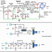
It is impossible to give good reply with so little information about power supply used.
Bridge or separate diodes for a few mA at ~200Vdc (HT) as used in this DI shouldn't get hot. In many other similar projects they are at around ambient temperature.
If you regulated heater then 1N5822 diodes can perform better because they don't get hot at those currents, low drop regulators as LM1084 instead LM317 also work well because they don't need big heatsink. Such changes are not really necesary with properly chosed psu transformer.
I don't know where alleged 47u capacitor is, value for HT should be more like 470uF and 4700uF for heaters. If you could touch it and circuit works properly then heat probably comes from very hot diodes or whatever is close to it. If you followed shcematic some heat is ok, components which can be touched often aren't too hot, so don't replace what works.
Be careful around power supply because currents there can be lethal!!!
AZ999 said:It is impossible to give good reply with so little information about power supply used.
Bridge or separate diodes for a few mA at ~200Vdc (HT) as used in this DI shouldn't get hot. In many other similar projects they are at around ambient temperature.
If you regulated heater then 1N5822 diodes can perform better because they don't get hot at those currents, low drop regulators as LM1084 instead LM317 also work well because they don't need big heatsink. Such changes are not really necesary with properly chosed psu transformer.
I don't know where alleged 47u capacitor is, value for HT should be more like 470uF and 4700uF for heaters. If you could touch it and circuit works properly then heat probably comes from very hot diodes or whatever is close to it. If you followed shcematic some heat is ok, components which can be touched often aren't too hot, so don't replace what works.
Be careful around power supply because currents there can be lethal!!!
thanks for the response. this is the schematic i used. sorry, i just assumed this was the one everyone based theirs off of!
andyfromdenver
Well-known member
If your layout is really tight, is it getting warm from a nearby resistor? What is your DC voltage post rectifier? Check at first power on (before it settles) and after being on for 20 seconds.mp5hkm said:Finally got around to building this guy. It sounds absolutely wonderful and has NO noise whatsoever but the 47uf capacitor after the bridge is getting pretty hot. (doesnt burn me and im able to leave my finger on it)
Just wondering if this is normal?
Also not sure how hot the bridges are suppose to get. They definitely get warm.
Currently getting 175v on plates, and 6.3v on heaters.
using 220 ohm resistor on each cathode and bypassing with 470uf cap.
You're probably fine. Congrats on an awesome DI. I posted my two tube eq version in my sig.
If it's your first tube project, please be careful touching anything in there.
Andrew
andyfromdenver said:If your layout is really tight, is it getting warm from a nearby resistor? What is your DC voltage post rectifier? Check at first power on (before it settles) and after being on for 20 seconds.
You're probably fine. Congrats on an awesome DI. I posted my two tube eq version in my sig.
If it's your first tube project, please be careful touching anything in there.
Andrew
thank you for the reply, Andrew.
The bridge rectifier, 39k resistor and first smoothing cap are pretty close together.
i’ll measure the rectified voltage when i get home later today, currently out of town.
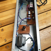
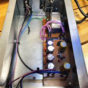
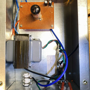
here is what it looks like. Only box i had laying around, kind of large... hah.
andyfromdenver
Well-known member
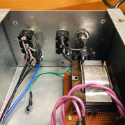
Looks like a tweed bassman chassis, cool. That's nice for putting lots of space between the power and output transformer.
I think it will be hard to check some voltages on the perf board, so as long as it's not melting, maybe just box it up and have fun!
If you'll permit my advice/ opinion (which may vary from the experts) I would construct a future one on a turret/ eyelet board or using tag strips, for sturdy-ness. Not to mention it's a nice low parts count project for point to point wiring. Keep in mind an end user, you may sell this on, and you know how musicians can really knock their gear around.
I was making these boxes for people a while ago and Drive by Truckers bought two for their live show. I had constructed it with the tube sitting outside the chassis with a tube cover, and oh man, after one year, I had to really beef it up, it was kind of frightening, actually. Since then, they made a custom travel case for it. I've since determined it is worth the hunt for a good/ big chassis to keep the tube inside.
Andrew
andyfromdenver said:Looks like a tweed bassman chassis, cool. That's nice for putting lots of space between the power and output transformer.
I think it will be hard to check some voltages on the perf board, so as long as it's not melting, maybe just box it up and have fun!
If you'll permit my advice/ opinion (which may vary from the experts) I would construct a future one on a turret/ eyelet board or using tag strips, for sturdy-ness. Not to mention it's a nice low parts count project for point to point wiring. Keep in mind an end user, you may sell this on, and you know how musicians can really knock their gear around.
I was making these boxes for people a while ago and Drive by Truckers bought two for their live show. I had constructed it with the tube sitting outside the chassis with a tube cover, and oh man, after one year, I had to really beef it up, it was kind of frightening, actually. Since then, they made a custom travel case for it. I've since determined it is worth the hunt for a good/ big chassis to keep the tube inside.
Andrew
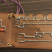
for sure about using a different board type! Had the perf board laying around, plus i wanted to have a go at soldering some traces
i’ve been looking for a chassis similar to the reddi and can’t find anything anywhere. any ideas?
andyfromdenver
Well-known member
mp5hkm said:for sure about using a different board type! Had the perf board laying around, plus i wanted to have a go at soldering some traces
i’ve been looking for a chassis similar to the reddi and can’t find anything anywhere. any ideas?
Looks really well done! I wiiish there was an off the shelf chassis like the REDDI. I view it as part of the thrill of DIY ;D trying to find something. I like to hunt thrift stores and flea markets. The tube mic power supply in the white market looks like a tidy box.
I can't recall the name of the one I used for my two tube version in my sig, but I found that on ebay and it's nice.
Take care!
Andrew
yvus said:Hello guys, and thank you for this great thread.
I am looking for the output tansformers used in this project, do you have any idea where I could find fitting ones ? is CJ still making them ?
Thanks !
I know people have used Carnhill 2290s.
MatthewMachinist
Member
- Joined
- Aug 19, 2020
- Messages
- 10
Hi Guys,
It looks like CJ isn't making his transformers anymore. So I am stranded without a transformer. I am brainstorming alternatives...
Does anyone have a spare CJ transformer they would be willing to sell me?
Does anyone know of another custom transformer maker who makes them as good as CJ did?
I am also thinking of contacting the maker of the Zod DI to see if he will sell me one of his, I imagine they are quite similar.
Has anyone tried the Carnhill 2290 and compared it to the Reddi or CJs transformer, is it as good?
I have though about contacting some transformer makers myself but I am at a loss to describe all of the specifications that would be required to communicate exactly what I want.
Similar threads
- Replies
- 55
- Views
- 8K