I would like to add ADC Overflow indicator with hold (approx 5sec) to AK5385A chip but I'm not sure about circuit to go with :/ any recomendations? ")


thanks, I willGoogle some "peak hold" circuits
Wow, yes, I was blind when I was reading AK5385A datasheet :/ definately pin 9 "Analog Input Overflow Detect PinRochey said:Theres no need for an extra analog detector. The adc already has an overflow pin!
Take the output of the pin through a diode, and into a parallel r and c (both connected to ground on one side.. Take the signal side into high impedance buffer, such as a fet or opamp.
The decay time will be defined by the vale of r and c.
Thanks, do you have some circuit example?JohnRoberts said:It is probably easier to make a simple hold circuit with cap and buffer. No need for a precise hold time.
JR
Rochey said said:" Take the output of the pin through a diode, and into a parallel r and c (both connected to ground on one side.. Take the signal side into high impedance buffer, such as a fet or opamp"
Thanks JohnI experimented a bit with this, but thing I really don't like is the LED light fade. I was afraid of that but I was not lazy to try it. What can I do about it?JohnRoberts said:This seems pretty simple... Rochey already suggested a simple circuit.
To break it down you need to convert a brief logic 1 (?) from the IC, to a longer duration current fed through a LED .
Starting with Rochey's suggestion toRochey said said:" Take the output of the pin through a diode, and into a parallel r and c (both connected to ground on one side.. Take the signal side into high impedance buffer, such as a fet or opamp"
Anode end of simple signal diode connects to the overflow pin.
Cathode (banded) end of diode connects to both a capacitor and resistor.
Other end of capacitor connects to ground.
The other end the resistor could be connected to ground.
When the overflow flag momentarily goes high, it will charge up the cap relatively quickly. When the overflow flag goes low the cap will slowly discharge at the RxC rate. You could almost connect a high efficiency LED directly to the cap through a current limit resistor, but that will not give much hold time and load the logic output
A very simple current buffer could connect the ground end of the discharge resistor to the base of a general purpose NPN transistor instead. Connect the emitter of that NPN transistor to ground. Connect the LED with a current limit resistor in series between a +V supply and the NPN collector. Connect the LED anode to +V, the LED cathode to the current limit resistor then collector.
Selecting values for this will be good mental exercise, but the circuit should work with a fairly wide range of values.
Good luck...
JR
HysteresisMoby said:I experimented a bit with this, but thing I really don't like is the LED light fade. I was afraid of that but I was not lazy to try it. What can I do about it?JohnRoberts said:This seems pretty simple... Rochey already suggested a simple circuit.
To break it down you need to convert a brief logic 1 (?) from the IC, to a longer duration current fed through a LED .
Starting with Rochey's suggestion toRochey said said:" Take the output of the pin through a diode, and into a parallel r and c (both connected to ground on one side.. Take the signal side into high impedance buffer, such as a fet or opamp"
Anode end of simple signal diode connects to the overflow pin.
Cathode (banded) end of diode connects to both a capacitor and resistor.
Other end of capacitor connects to ground.
The other end the resistor could be connected to ground.
When the overflow flag momentarily goes high, it will charge up the cap relatively quickly. When the overflow flag goes low the cap will slowly discharge at the RxC rate. You could almost connect a high efficiency LED directly to the cap through a current limit resistor, but that will not give much hold time and load the logic output
A very simple current buffer could connect the ground end of the discharge resistor to the base of a general purpose NPN transistor instead. Connect the emitter of that NPN transistor to ground. Connect the LED with a current limit resistor in series between a +V supply and the NPN collector. Connect the LED anode to +V, the LED cathode to the current limit resistor then collector.
Selecting values for this will be good mental exercise, but the circuit should work with a fairly wide range of values.
Good luck...
JR
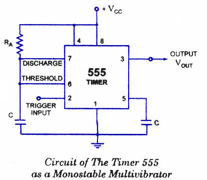
I tried already but not a big improvement. So, Monostable Multivibrator is the way to go . Not 555 because it needs negative impulse, maybe SN74LS02 or so...JohnRoberts said:Feature creep, like adding snap action hysteresis requires more parts and makes the consulting bill more expensive.
Of course one simple thing to try is to add one more resistor from the base to ground, that should turn it off a little sharper.
JR
Rochey said:Wouldn't a comparator do the trick?
The really clever solution is to write the slowly dimming LED into the marketing spec so it becomes a feature instead of a fault.JohnRoberts said:The issue with the transistor turning off too slow is because it is operating in base current amplification mode to multiply that base current to drive the collector load. Instead driving the base with a voltage (fraction of the cap voltage divided down) will cause the current to drop more quickly (exponentially) between full on at say .7 and full off at say .4V
It was probably 30y ago I was playing with this types of circuits. Looks funny nowJohnRoberts said:Google up the old school two transistor flip-flop. IIRC It's called an "astable multi-vibrator" or something like that. Simply uses hysteresis or positive feedback to snap into one mode, then snap back to steady state mode.
A 555 timer is easy but not the same educational experience. Once upon a time transistor FF were how it was done, before the rise of ICs.
JR
but it works with bit of tweaking Enter your email address to join:
