Would like to discuss Neumann CMV5b mic schematic with EF12k tube

GroupDIY Audio Forum

Help Support GroupDIY Audio Forum:

This site may earn a commission from merchant affiliate links, including eBay, Amazon, and others.

bernbrue

Well-known member
Joined
Mar 13, 2006
Messages
1,516
Location
Wolfenbüttel - Germany
Hi,
I did some searching for a dedicated EF12k mic schematic and stumbled over the CMV5b bottle mic. I´ve got almost all part together and wonder what to take into consideration before building the mic according to the attached schematic. I´ve read excellent reviews about this mic which was built with various different tubes (VF14 with BV8 transformer as well). It is supposed to be an outstanding mic with sonic qualities comparable to the legendary U47. Since I´m going to built it into a U47 style body, the latter aspect seems to be quite interesting.

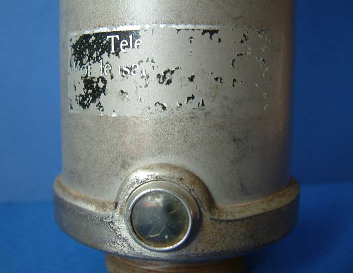
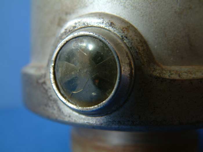
I know, don´t believe what people say, just built it and listen yourself. But my interest is specially related to the psu (half wave rectified H+ with stabilzer tube and negative heater supply), the hiZ area (50Meg) which I might replace with higher value resistors and this funny "Betriebsanzeige" that was used in old telephones as well (internal resistance is 6,5 Ohms). The bias of the EF12 is achieved by the heater voltage. Any hints, suggestions and warnings are welcome.
regards
Bernd
 

Attachments

  • CMV5b schematic better resolution.JPG
    CMV5b schematic better resolution.JPG
    867.1 KB · Views: 164
DSCF0012.jpg


DSCF0013.jpg


It indicates that the microphone is ON.
regards
Bernd
 
So what is that a lamp??
I was reading that this mic used the same transformers as the 47?
but tube is kinda obsolete!
 
Yes that´s true, same transformer as the U47 in combination with VF14 tube. The early versions used a RE084k tube and a 5:1 transformer. Do you refer to the lamp in the psu or the "Betriebsangzeige", indicating that the mic is switch ON? I wonder whether the tube in the psu could be substituted by string of diodes.
regards
Bernd
 

Attachments

  • Schaltung Neumann-Flasche.jpg
    Schaltung Neumann-Flasche.jpg
    31 KB · Views: 62
benqbasic said:
Excuse my ignorance but what is the beach ball type cymbal coming off the heater?
It was a device commonly used in telephone exchanges at the time. Some kind of ferromagnetic galavanometer.
"Betriebsanzeige" translates as power indicator.
 
bernbrue said:
But my interest is specially related to the psu (half wave rectified H+
The only justification for half-wave rectification is that solid-state rectifiers at the time were not capable of handling the high voltage, so they had to put two in a doubler - using them in a full-wave rectifier would have meant using 4 of them.
with stabilzer tube
I'm not sure the tube here provides much regulation. It is connected in series with a 30k resistor and tries to fight against 60k coming from the rectifier. In the best case the regulation factor is 2:1.
The bias of the EF12 is achieved by the heater voltage. Any hints, suggestions and warnings are welcome.
As a consequence, the heater voltage must be super clean, because it superimposes directly on the signal delivered by the capsule. The two inductors are crucial in that role.
 
Thanks for your response, abbey road.
I´m not convinced to build the psu as shown in the schematic. The MK7 passive psu looks fine for this circuit. I would have to make the heater voltage negative but otherwise it should work. The "Betriebsanzeige" will be replaced by a 6,5 Ohm resistor. Any comments on increasing the highZ resistors? I would take 200 Megs here instead. I´m going to try a 5:1 Telefunken transformer and different values for the output cap, since these mics were mainly used  for speakers and anouncers, less for musical purpose. When time allows I start building the mic and report back. 
regards
Bernd
 
bernbrue said:
Any comments on increasing the highZ resistors? I would take 200 Megs here instead. I´m going to try a 5:1 Telefunken transformer and different values for the output cap, since these mics where used mainly for speakers and anouncers, less for musical purpose.
As it is, the LF cut-off is at about 100Hz, which is just right for compensating the proximity effect. You can increase the first resistor (the one that bias the capsule almost as much as you want. The other (grid resistor) can also be increased, but doing so increases grid-current bias. It shouldn't be a problem with a healthy tube.
 

Latest posts

Back
Top