


gemini86
Well-known member
Docs:
Original Schematic
Schematic with mods and added filtering :: NEW
Layout
Faceplate
BOM :: UPDATED 4/13/2013
Toure14's Mouser cart This cart has not yet been verified (as of 5/13/20013). Please use at your own discretion.
This is (mostly) a straight forward build, but here are a few tips for you guys geeks are building the GIX-51X preamp for a 51X rack.
I shouldn't have to say this, but to some of you: Use a new soldering tip. If it's got black spots where no solder will stick, or the tip isn't sharp, you need a new one. This will help eliminate cold solder joints and make everything go faster.
Place the 1mm pin sockets onto a tube, like so:
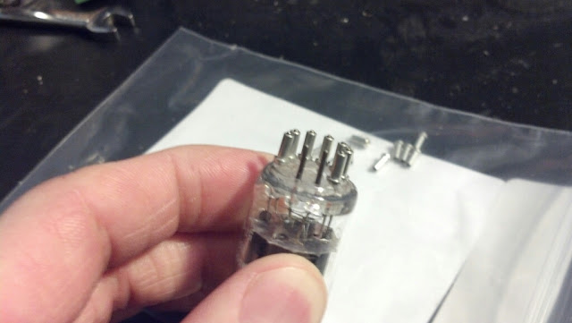
They shouldn't be a super snug fit.
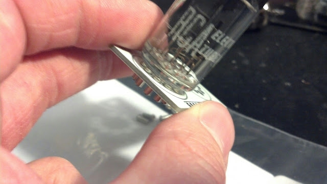
Place the sockets and tube into the tube PCB, set it on its side on the table just to tack solder on of the pins so it stays put. This next part is a little tricky, I like to place the tube in my hand upside down and reflow the solder tack as i level the pin sockets.
Make sure all the sockets are flat to the top side of the board:
I usually tack a socket on the opposite side to make sure it stays flat where I want it, then put the pcb in a third-hand clamp.
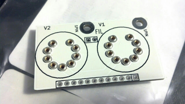
Solder all the sockets, double check the top to make sure everything is level.
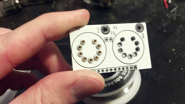
They look so happy! That's because they know how awesome they are.
Who's the idiot who let "1PIN" get through to the final gerber? I AM!
Oh well. This board can be set aside for now.
Now the control board-
READ ME!!! This is important! There are two SPDT toggles, one of them is on-off-on, the other is on-on. The one with only two position is SW4. It goes on the right side. The on-off-on is for the HPF and goes in the middle.
Also make sure to have all the notches on the switch bushings going the same way, so it doesn't drive you crazy later. ...because it will.
Stuff all the resistors and the two HPF caps FIRST. This PCB will hold all our front panel controls, so there's really no need for any of the anti-rotation locating tabs that come on the pot and rotary switch. Just snip em off.
That little round peg needs to go.
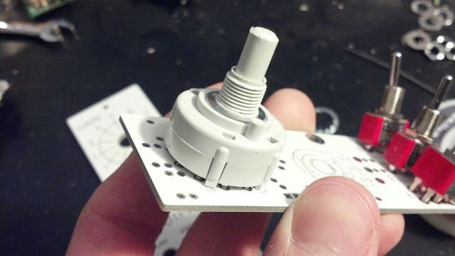
You will ruin everything if you don't do this and I'm not going to feel bad for you.
[Note: The alpha switch version of this switch will also work. It's from Taiwan, but personally, I've been seeing better quality with them than with the Lorlin switches.]
Now, I had soldered the big rotary switch in first, but you could probably do them all at once. AGAIN, stuff the resistors first, despite what you see in these photos. It's not a game ender, but some of the resistors are close to the rotary switch. You'll end up melting some plastic, and that will make you look dumb if you ever want to show off your handy-work.)
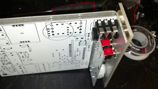
Remove all the nuts and washers from the toggles, except for one, use that one as a stopper to get the right clearance between the pcb and faceplate.
Bolt the faceplate to the switch, this will help you line up all the toggles in their holes.
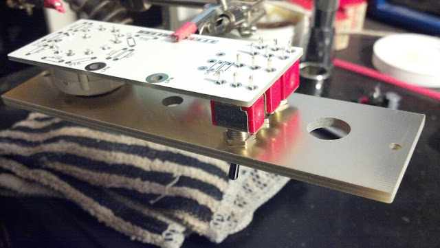
Double check everything (triple check that the on-off-on switch is in the middle, not the right side!) Solder them in.
Remove the faceplate from the switches. Grab your metal bracket (if you have one) and place the potentiometer (sans locating tab) through it and into the faceplate hole. I made these hold snug on purpose, BUT- it appears that the fab house won't be winning any awards for precision there. Some of them are very snug, so you can actually thread the faceplate onto the pot bushing. I actually prefer this but this will possible create a NEW problem: While the main board will be serviceable and removable, the controls board will be stuck onto the faceplate and bracket permanently. I'd double check your gain resistors for errors and check the soldering joints. If this is something you don't want to worry about, you have to open up the hole a tiny bit with a drill (just use it as a reamer) or a small round file.
Get the pot flush to the faceplate or bracket, you will see that the pins look like they're too short. Stop whining, they're not too short.
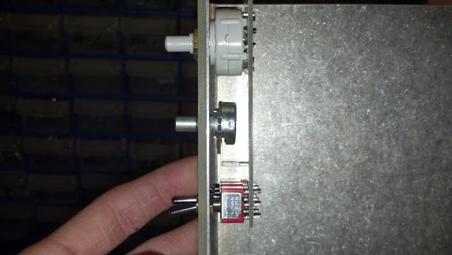
Okay they're kindof short, but they're just about flush with the back of the control pcb. Solder them in place with plenty of solder. A cold joint here would be easy to accomplish if you have a dirty tip.
Not pictured (because I forgot to take a picture of it) is the SIL connector on the control board. It goes on the back side facing the rear of the unit, in case that was not obvious. Now you're done with the control board.
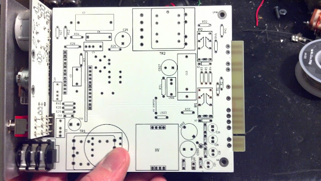
Populate the main board with all the small components- caps, resistors, relays, for now just ignore the two pads marked "FIL". Also, do not solder in the instrument jack just yet.
I cut all my leads very very short after soldering but this is especially needed in the power cap section, more specifically c26 and c27. They will be awful close to the bracket mounting legs and while they do not touch on my build, they can and WILL cause a dead short to ground if you have a long lead sticking out into it.
See here:
Nothing touches, no shorts. Make sure all the leads are cut as short as possible! Double check with an ohm meter on all the power rails to be sure you have no continuity to the bracket.
Now, before you solder the instrument jack to the board, make sure it's perfectly flush with the front edge of the PCB. Bend the leads so it will hold itself to the board, and tack one of the leads closest to the bottom edge. You may want to test fit it in the bracket/faceplate now. Don't use any of the supplied black plastic washers, just the one bezel for the front. Just mount it hand tight, then check PCB alignment.
The mounting holed should all line up perfectly. You may go as far as screwing down the rear of the board to the bracket. Then if an adjustment is needed, just reflow the one tack you did and get it all straight and legit, son. The board should be flush to the bottom of the jack.
Everything all lined up:
The mounting holes in the bracket on the rear legs are just the right size to hand thread a 4-40 screw without a nut needed on the backside. Thread it through and cut the excess off so they don't interfere with other modules in your rack.
A couple notes on the main board:
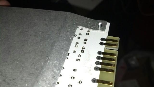
1) Mounting the tube board to the main board: The outline on the main board shows exactly where the tube board should be located. It needs to be very flush to the main board, no space under it or you'll be penalized for going out of bounds. A SIL12 90 degree header could work here, but the plastic retaining block will get in the way. I just used solid core wire, or a bunch of little resistor leads off the floor.
2) The pin head under the main board, which connects to the control board IS meant to be a 90 degree SIL12 header. Plug it into the header socket on the control board, THEN move the main board into position and make sure everything is fit correctly. Also make sure you've stuffed C10 first, and that it's leads have been clipped as short as possible or you'll run into trouble.
:: NEW NEW NEW NEW NEW NEW NEW NEW NEW NEW ::
3) Add a 200R resistor at "HV JUMPER" on the main board. Add the new 100nF/250V ceramic cap to the underside of the board as shown in this photo by bruce0:
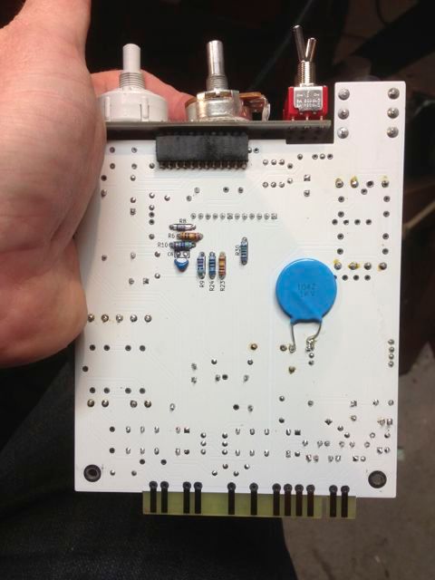
It goes from the L503/HV JUMPER junction to ground and adds another filtering stage to the HV supply before it hits the output tubes.
The HV converter is very straight forward. I didn't take any pics, because there's not much to see.
1) Solder down the MAX1771CPA+ first. If you've never hand soldered SOIC8 parts, check youtube, plenty of videos that show you how to do it.
2) Solder the current sense resistor. Make sure it's flat to the pcb, tack one side, solder the other, then add solder to the first side.
3) Solder down the inductor. Same as anything else.
4) Solder the surface mount diode. You may need to move it a tad closer to the inductor than is laid out on the pcb, to make room for the electrolytic cap next to it.
5) Solder in all resistors and caps, except C501.
6) Solder in Q501, which goes on the bottom of the board, bent at 90 degrees, leaving some space under it so it's not touching anything. It's not required, but a good idea to place some electrical tape or heatshrink on the back of the tab, so nothing shorts to the bottom of the board.
7) Solder in U502 and C501.
8) Solder in the two pin headers. I put the pin sockets on the converter board and the pins on the main board but in this case it doesn't matter much. The unit will be pretty much drained of HV when removed from the rack so you don't have to worry about zapping yourself on exposed pins. (just, please don't stick it to your tongue.)
:: NEW NEW NEW NEW NEW NEW NEW NEW ::
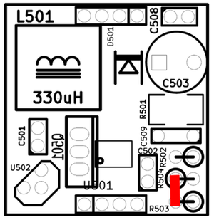
9) Add a 100nF wima cap across R504/R503 to ground. This will stabilize the HV output and prevent oscillations.
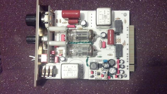
That's all for now. Here's my finished unit:
Andoids are great, but my camera sucks compared to an Iphone. Let's get it together, Motorola.
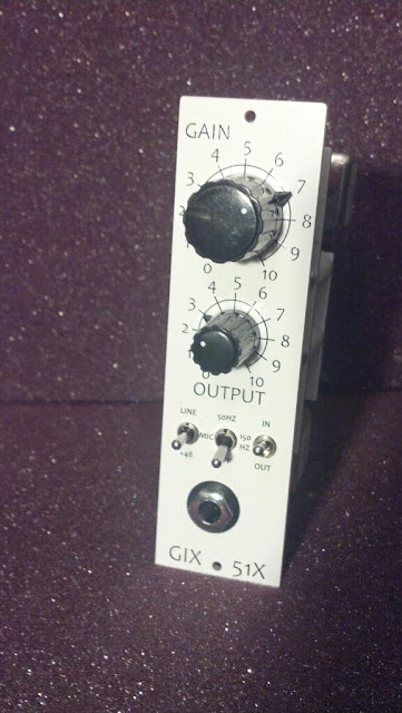
Love this knob combo on the white faceplate. Schematic with mods and added filtering
Original Schematic
Schematic with mods and added filtering :: NEW
Layout
Faceplate
BOM :: UPDATED 4/13/2013
Toure14's Mouser cart This cart has not yet been verified (as of 5/13/20013). Please use at your own discretion.
This is (mostly) a straight forward build, but here are a few tips for you guys geeks are building the GIX-51X preamp for a 51X rack.
I shouldn't have to say this, but to some of you: Use a new soldering tip. If it's got black spots where no solder will stick, or the tip isn't sharp, you need a new one. This will help eliminate cold solder joints and make everything go faster.
Place the 1mm pin sockets onto a tube, like so:
They shouldn't be a super snug fit.
Place the sockets and tube into the tube PCB, set it on its side on the table just to tack solder on of the pins so it stays put. This next part is a little tricky, I like to place the tube in my hand upside down and reflow the solder tack as i level the pin sockets.
Make sure all the sockets are flat to the top side of the board:
I usually tack a socket on the opposite side to make sure it stays flat where I want it, then put the pcb in a third-hand clamp.
Solder all the sockets, double check the top to make sure everything is level.
They look so happy! That's because they know how awesome they are.
Who's the idiot who let "1PIN" get through to the final gerber? I AM!
Oh well. This board can be set aside for now.
Now the control board-
READ ME!!! This is important! There are two SPDT toggles, one of them is on-off-on, the other is on-on. The one with only two position is SW4. It goes on the right side. The on-off-on is for the HPF and goes in the middle.
Also make sure to have all the notches on the switch bushings going the same way, so it doesn't drive you crazy later. ...because it will.
Stuff all the resistors and the two HPF caps FIRST. This PCB will hold all our front panel controls, so there's really no need for any of the anti-rotation locating tabs that come on the pot and rotary switch. Just snip em off.
That little round peg needs to go.
You will ruin everything if you don't do this and I'm not going to feel bad for you.
[Note: The alpha switch version of this switch will also work. It's from Taiwan, but personally, I've been seeing better quality with them than with the Lorlin switches.]
Now, I had soldered the big rotary switch in first, but you could probably do them all at once. AGAIN, stuff the resistors first, despite what you see in these photos. It's not a game ender, but some of the resistors are close to the rotary switch. You'll end up melting some plastic, and that will make you look dumb if you ever want to show off your handy-work.)
Remove all the nuts and washers from the toggles, except for one, use that one as a stopper to get the right clearance between the pcb and faceplate.
Bolt the faceplate to the switch, this will help you line up all the toggles in their holes.
Double check everything (triple check that the on-off-on switch is in the middle, not the right side!) Solder them in.
Remove the faceplate from the switches. Grab your metal bracket (if you have one) and place the potentiometer (sans locating tab) through it and into the faceplate hole. I made these hold snug on purpose, BUT- it appears that the fab house won't be winning any awards for precision there. Some of them are very snug, so you can actually thread the faceplate onto the pot bushing. I actually prefer this but this will possible create a NEW problem: While the main board will be serviceable and removable, the controls board will be stuck onto the faceplate and bracket permanently. I'd double check your gain resistors for errors and check the soldering joints. If this is something you don't want to worry about, you have to open up the hole a tiny bit with a drill (just use it as a reamer) or a small round file.
Get the pot flush to the faceplate or bracket, you will see that the pins look like they're too short. Stop whining, they're not too short.
Okay they're kindof short, but they're just about flush with the back of the control pcb. Solder them in place with plenty of solder. A cold joint here would be easy to accomplish if you have a dirty tip.
Not pictured (because I forgot to take a picture of it) is the SIL connector on the control board. It goes on the back side facing the rear of the unit, in case that was not obvious. Now you're done with the control board.
Populate the main board with all the small components- caps, resistors, relays, for now just ignore the two pads marked "FIL". Also, do not solder in the instrument jack just yet.
I cut all my leads very very short after soldering but this is especially needed in the power cap section, more specifically c26 and c27. They will be awful close to the bracket mounting legs and while they do not touch on my build, they can and WILL cause a dead short to ground if you have a long lead sticking out into it.
See here:
Nothing touches, no shorts. Make sure all the leads are cut as short as possible! Double check with an ohm meter on all the power rails to be sure you have no continuity to the bracket.
Now, before you solder the instrument jack to the board, make sure it's perfectly flush with the front edge of the PCB. Bend the leads so it will hold itself to the board, and tack one of the leads closest to the bottom edge. You may want to test fit it in the bracket/faceplate now. Don't use any of the supplied black plastic washers, just the one bezel for the front. Just mount it hand tight, then check PCB alignment.
The mounting holed should all line up perfectly. You may go as far as screwing down the rear of the board to the bracket. Then if an adjustment is needed, just reflow the one tack you did and get it all straight and legit, son. The board should be flush to the bottom of the jack.
Everything all lined up:
The mounting holes in the bracket on the rear legs are just the right size to hand thread a 4-40 screw without a nut needed on the backside. Thread it through and cut the excess off so they don't interfere with other modules in your rack.
A couple notes on the main board:
1) Mounting the tube board to the main board: The outline on the main board shows exactly where the tube board should be located. It needs to be very flush to the main board, no space under it or you'll be penalized for going out of bounds. A SIL12 90 degree header could work here, but the plastic retaining block will get in the way. I just used solid core wire, or a bunch of little resistor leads off the floor.
2) The pin head under the main board, which connects to the control board IS meant to be a 90 degree SIL12 header. Plug it into the header socket on the control board, THEN move the main board into position and make sure everything is fit correctly. Also make sure you've stuffed C10 first, and that it's leads have been clipped as short as possible or you'll run into trouble.
:: NEW NEW NEW NEW NEW NEW NEW NEW NEW NEW ::
3) Add a 200R resistor at "HV JUMPER" on the main board. Add the new 100nF/250V ceramic cap to the underside of the board as shown in this photo by bruce0:
It goes from the L503/HV JUMPER junction to ground and adds another filtering stage to the HV supply before it hits the output tubes.
The HV converter is very straight forward. I didn't take any pics, because there's not much to see.
1) Solder down the MAX1771CPA+ first. If you've never hand soldered SOIC8 parts, check youtube, plenty of videos that show you how to do it.
2) Solder the current sense resistor. Make sure it's flat to the pcb, tack one side, solder the other, then add solder to the first side.
3) Solder down the inductor. Same as anything else.
4) Solder the surface mount diode. You may need to move it a tad closer to the inductor than is laid out on the pcb, to make room for the electrolytic cap next to it.
5) Solder in all resistors and caps, except C501.
6) Solder in Q501, which goes on the bottom of the board, bent at 90 degrees, leaving some space under it so it's not touching anything. It's not required, but a good idea to place some electrical tape or heatshrink on the back of the tab, so nothing shorts to the bottom of the board.
7) Solder in U502 and C501.
8) Solder in the two pin headers. I put the pin sockets on the converter board and the pins on the main board but in this case it doesn't matter much. The unit will be pretty much drained of HV when removed from the rack so you don't have to worry about zapping yourself on exposed pins. (just, please don't stick it to your tongue.)
:: NEW NEW NEW NEW NEW NEW NEW NEW ::
9) Add a 100nF wima cap across R504/R503 to ground. This will stabilize the HV output and prevent oscillations.
That's all for now. Here's my finished unit:
Andoids are great, but my camera sucks compared to an Iphone. Let's get it together, Motorola.
Love this knob combo on the white faceplate. Schematic with mods and added filtering
Last edited:
 I'm not exactly...experienced when it comes to shipping, so I've been doing what I can as I go. Will be restocking and shipping this week. I will hopefully have everyone shipped out by end of next week.