100V DC supply design

GroupDIY Audio Forum

Help Support GroupDIY Audio Forum:

This site may earn a commission from merchant affiliate links, including eBay, Amazon, and others.

desun

Well-known member
Joined
Apr 24, 2008
Messages
60
Location
Denver, CO (formerly UK)
So I have a Sanken mic that is missing it's power supply, it needs a 100VDC supply. However, i'm unsure the best method for this-- do I go with the 'standard' tube-style supply:
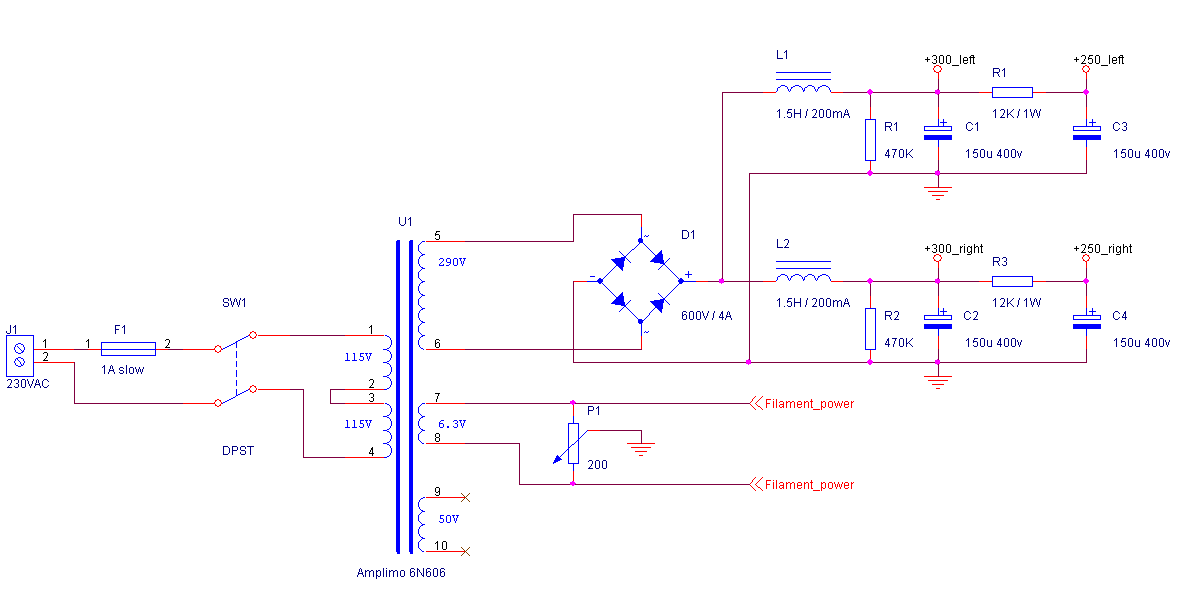
tube-power.png


or can I do it another way with a regulator? There doesn't seem to be 90-110v regulators around, but can I put a Zener on the ground pin of a 78 series regulator, and just make sure the input voltage is not too wide?

Current consumption of the mic is low, but obviously i'd like it to have as minimal ripple as is sensible to design in!

Thanks
 
Brian Roth said:
The TL783 3-terminal regulator is rated up to 125 VDC input to output.

Bri

And to get it to regulate only needs an excess voltage of 20V. You could use my phantom power circuit and just tweak one resistor to get the voltage you want. I have already experimented with this to make a 275V regulated supply and it works well. You just have to be careful not to accidentally short the output as that is guaranteed to blow up the TL783 in my circuit as it stands and it is a sod to change. You need to add a 30V or so zener across the TL783 to prevent that.

Cheers

Ian
 
> Current consumption of the mic is low, but obviously i'd like it to have as minimal ripple

These go together. Low current means you can use quite large R in an affordable, simple, and *reliable* R-C filter.

Example. Find a 120v AC secondary. Rectify to DC, 165V DC. You want 100V DC, so 65V drop. Say the mike pulls 2mA. 65V/2mA= 32K total resistance needed.

You want roughly one R-C filter stage for every gain stage from here to the loudspeaker. A minimal PA system would have 5 tube gain-stages.

Or: you can reasonably get 20dB-40dB in one R-C filter stage. Say the ripple at 165V is 10%, 16V. Say the mike noise-level is 1 microVolt. 16V/1uV= 144dB reduction needed. 5 R-C stages at 30dB per stage does it.

So six caps and five resistors. 32K/5= 6K or 7K each. 30dB reduction of 100Hz ripple requires the cap impedance at 100hz to be 32 times smaller than the resistor. 6K/32= 200 ohms.

10uFd 200V is very affordable, try that. 10uFd at 100Hz is 159 ohms, fine.

The first cap could possibly be 1uFd per mA. For 2mA, 2uFd. Go higher, use 10uFd here. (Caps are cheaper when you buy more all the same.)

Simulated, this gives 104V with 6 NANO Volts ripple. Better than we need. (Better than any simple regulator!) This is because everything was rough approximations rounded-up just-to-be sure. In fact we could chop off one R-C stage, 5 caps and 4 resistors, 10u-8K-10u-8K-10u-8K-10u-8K-10u, get 102V at 100 nanoVolts ripple.

Caps are cheap today. 40u-10K-20u-10K-20u-10K-20u also gives 100 nanoVolt ripple. However do not try this with a "can cap" with common negative, use separate caps.

That plan costs $6. Slightly more than a regulator, but HV regs still need that first cap, need various protections (added parts) and probably still want a final R-C clean-up at the end.
 
However do not try this with a "can cap" with common negative, use separate caps.

Hi PRR,

Can you say a bit more about that? Obviously a lot of tube amps do this. Is there a reason why it is a bad idea to use old-style dual-caps, apart from the cost?

Thanks!

Stewart
 
PRR said:
That plan costs $6. Slightly more than a regulator, but HV regs still need that first cap, need various protections (added parts) and probably still want a final R-C clean-up at the end.

+1

Cheers

Ian
 
> a lot of tube amps do this

Not to get _all_ the way from raw rectifier down to mike capsule.

The mighty spikes through the rectifier loop will contaminate the final output.

Designs varied, but even a phono stage would usually have its own final B+ filter can.

There is the Heath Mono preamp.... ah, but it started with semi-smooth DC from your power amp. Even so it was never dead-clean.
 
I'd do a simple raw supply with a 2-stage filter, then hang a zener on the base of an emitter follower, bypassing the zener and output w. caps. If the emitter follower is a pair of transistors in a Darlington configuration, all the better.

Peace,
Paul
 
I would think the transistor/Darlington would need to have high voltage ratings, since the base would be at ground potential until the capacitor across the Zener charged up, yet the collector would be at full B+ during that time.

That brought back a memory, and sure enough, I have the schematic.  The (in?)famous Audio Research SP-3A tube hifi preamp from the 1970's used that same sort of circuit.  The "pass" transistor is listed as a DT5410 on the schemo (I didn't seem to find any info on that part via Google).  There are nine 47V Zeners from the base to ground.  Schemo shows 500V raw DC on the collector and 440V on the emitter.  Hmmmm....47 x 9 = 423V.....oh, well...just reading off the schemo.

Bri
 
That's a very nice looking schematic in the first post. I am always on the lookout for good schematic capture tools. What did you use to draw this?

Cheers

Ian
 
Back
Top