Single External Power Supply for ±15V and +48V

GroupDIY Audio Forum

Help Support GroupDIY Audio Forum:

This site may earn a commission from merchant affiliate links, including eBay, Amazon, and others.

Rochey

Well-known member
White Market Member
Joined
Jul 2, 2004
Messages
2,697
Location
Dallas, TX - Formerly UK
Hello Folks,

quick intro. Expat Audio makes an Uber Power supply board, that takes the output of a secondary transformer, filters some of the noise, then runs it through regulators,while also using a voltage multiplier to create a Phantom power rail.

Phew, that is a mouthful!

Okay - here comes the mod details. I'm a chicken when it comes to mains power. It makes me nervous. This combined with some feedback I received regarding the Eden Preamps made me look into using an external wall wart (power supply) to make the power supply, rather than having a mains power IEC connector, then a toroidal transformer in my design.

The trouble with external power supplies (or wall warts as I like to call them) is that their output is single ended. It swings above ground, the it swings negative. This means a few things:
a) When its rectified, you get an output voltage similar to that of a half bridge rectifier (y'all can google that if you like)
b) One output can be present before the other.

That has two knockon effects
a) More ripple before the regulators. To compensate, one can add greater capacitance to slow down the sag, or simply start at a higher voltage!
b) With a balanced toroidal, each regulator sees voltage at the same time. But, in a single ended input, on startup, one regulator will start before the other. That means the output of the one that hasn't started may see voltage from the other. Eeek. Not good.


We can compensate for this on the Uber Power supply by simply adding diodes to the output of the regulators, which allows voltage to flow out of the regulators, but not back in.

8415021071_73790654fb_z.jpg

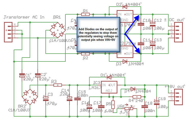
Schematic with modification details

8414984019_932cbfa4cb_z.jpg

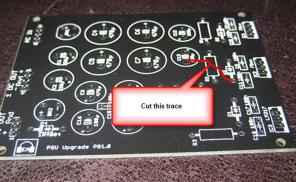
Trace to cut on the top of the Uber PSU board

8416079674_46c5581e7b_z.jpg

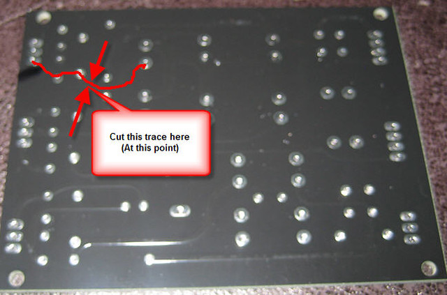
Trace to cut on the bottom of the Uber PSU Board
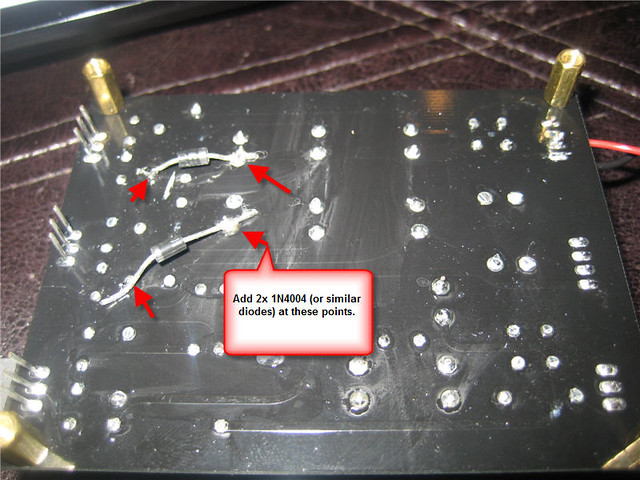
8416079664_887d0d107e_z.jpg

Diodes to Add

Those diodes should be soldered on to the legs of the appropriate capacitors.

External Power Supply Notes:

These modifications, along with a 18VAC external power supply can support ±15V and +48V rails. I've found that 16VAC transformers don't drive the voltage multiplier high enough for the +48V regulator. However, if you're developing a system that doesn't require phantom power 16VAC will be sufficient.

Jameco has a lovely selection of AC to AC external power supplies. Please make sure you use an AC to AC supply.
Jameco Part no. 121216

I'll post a video showing multimeter readings soon.

/R
 
Rochey said:
b) With a balanced toroidal, each regulator sees voltage at the same time. But, in a single ended input, on startup, one regulator will start before the other. That means the output of the one that hasn't started may see voltage from the other. Eeek. Not good.

I'm not quite sure what real-world problem this mod is trying to fix, and whether your proposed fix will help or hurt.

The diodes you add, are these in series with the regulator output (so between the regulator and the capacitor)? This will negatively impact your regulators' output impedance, and do nothing to keep your rails from being pulled to the wrong polarity.

D2/D3 already give you some protection; one would then add diodes from each rail to ground. (This is, reportedly, still not enough for some 78xx/79xx-type regulators, which require a diode in their ground leg if the output could ever be pulled below GND).

JD 'confused' B.
 
Jd, i'll post an updated schem wheni get a chance this afternoon.

I'm essentially adding anti latchup diodes, at the price of dropping 0.6ish per output


R
 
I did many products powered by wall warts, and don't recall having to do mush special handling.

One engineer who worked for me, religiously put diodes in series with the ground leg of all his 3 terminal regulators. Apparently he got bit by latch-up problems in the past. The diode in the ground leg slightly reduces regulation quality, and increases output V approximately  .6V. 

I recall one design where he added extra circuitry to insure the PS rails would come up in one sequence only... this was to prevent/reduce turn on transients, from the outputs of unclamped opamps (In a mixer with tens of outputs you can't easily afford to clamp everything). In commercial designs the customers can be very sensitive to things like turn-on/off noise, often more than actual sonic performance. 

JR
 
Hello Folks,

lets put some more meat on the bone here.

The idea of the additional diodes is to stop the 7815 output seeing any voltage below ground.  (and the 7915 seeing anything above ground).
An opposite polarity on the output of these regulators can cause latchup problems that can stop the regulator from even starting.

This is only an issue when you have a single ended power supply as the 7915 may startup before the 7815.

The "wrap around" diodes around the regulators allows a path for capacitors to discharge when power is removed from the input.

I'm asked Keith to stop by with a few more details. He had some wonderful examples of consoles that have suffered this kind of issue.
I believe this link may have something to do with it: http://www.gearslutz.com/board/geekslutz-forum/47299-power-supply-common-mode-latch-up.html

Cheers

/R
 
Rochey said:
The idea of the additional diodes is to stop the 7815 output seeing any voltage below ground.  (and the 7915 seeing anything above ground).

I'll ask again: how does the diode help?

Suppose you have a diode in series with the 7815 output (anode to 7815, cathode to output capacitors). Now apply -5V to the cathode of this diode. What is the voltage at the output of the 7815?

Rochey said:
This is only an issue when you have a single ended power supply as the 7915 may startup before the 7815.

You also need a load directly between + and -. If all loads are ground-referenced, this situation cannot occur. (A 'load' here is not just an external load, any and all circuits/parts connected to the supply are loads in this context).

Is there any particular reason why you choose this fix over the traditional solution, as has been mentioned in this thread and others?

JDB.
 
Rochey said:
The "wrap around" diodes around the regulators allows a path for capacitors to discharge when power is removed from the input.

Just as a data point: LM317/LM337 and newer devices have those diodes built in.

-a
 
Andy Peters said:
Rochey said:
The "wrap around" diodes around the regulators allows a path for capacitors to discharge when power is removed from the input.

Just as a data point: LM317/LM337 and newer devices have those diodes built in.

-a
Is this valid for voltages above 25VDC or caps at reg.out >25uF when a crowbar cuts supply at reg.in ? (National and OnSemi advise in their app-notes to use protection diodes for these conditions).

For the fixed V regulators latching at startup when load is not connected to ground but between +/-rails (IE opamps,...), clamping diodes (not series diodes) between Vreg.out and gnd should help to prevent this, as JDB already pointed out.
See On Semiconductor, Linear and Switching Voltage Regulator Handbook pg.27-28 on this subject.
 
jdbakker said:
Rochey said:
The idea of the additional diodes is to stop the 7815 output seeing any voltage below ground.  (and the 7915 seeing anything above ground).

I'll ask again: how does the diode help?

Suppose you have a diode in series with the 7815 output (anode to 7815, cathode to output capacitors). Now apply -5V to the cathode of this diode. What is the voltage at the output of the 7815?
The 7815 will see zero volts at its output, referenced to zero volts.
Rochey said:
This is only an issue when you have a single ended power supply as the 7915 may startup before the 7815.

You also need a load directly between + and -. If all loads are ground-referenced, this situation cannot occur. (A 'load' here is not just an external load, any and all circuits/parts connected to the supply are loads in this context).

Is there any particular reason why you choose this fix over the traditional solution, as has been mentioned in this thread and others?

JDB.
I've been away from a desktop computer for a while, so it's taken me a while to get to this, but the idea is that this power supply should work under as many circumstances as possible, and since it may be connected to any number of loads, with a wide variety of possible circumstances and conditions.

You're quite right, the inter-rail connection has to "cross" zero volts, but this can and does happen in people's deigns.

An example:

Take a look at the switch lamp illumination on SSL products. -Where incandescent 'wedge' bulbs are used, they use 40V bulbs (for lowest current consumption at a given lamp power rating, they went with the highest voltages) and they connnect them between the positive and negative rails. (Slightly under-running them for longer service life, but BETWEEN THE RAILS with no ground reference. -And on power-up, any illuminated bulbs will instantaneously be at their lowest resistance, since they're at their coldest.)

There's a secondary circumstance which I've personally encountered, and it's an easy thing to test. -A few years ago  built a small multi-channel preamp for location recording, and I decided to build an outboard power supply 'brick'. the POWER connection between the two was a multi-pin XLR (4 or 5 pin, I forget, but I think I used the same connector and pin convention that GML uses on its power supply, where one PSU can 'loop through' to power several units, so you don't have to buy multiple power supplies.) This was with a convetional 16-0-16 transformer secondary, so there were no unusual 'tricks' or anything; everything was absolutely conventional.

I loaned it out once to someone who complained that it didn't work.

-I brought it home and tested it and it DID work. Perfectly.

He took it out again and called me saying that the damned thing DIDN'T work, and he had an orchestra waiting.

I drove out and discovered what the problem was. -One rail was latched in shut-down, because he and I connected things differently.

Whereas I connect everything BEFORE applying AC power, he had plugged everything into the AC power and THEN plugged everything else in. -When he plugged the XLR in, power was mated, of course some pins connect BEFORE others. This allowed a regulator to latch up. -It REALLY only takes milliseconds.

One final note about IC's. They FREQUENTLY allow rail-to-rail paths without passing "through" ground. (Do not pass go, do not collect $200) -Just look at a 5534. There's NO "zero volts" connection. There's a +ve and a -ve pin. -Yes, frequently, yes, people DO connect the non-inverting input to ground, when building inverting stages, or virtual-earth summing amplifiers... but that ground connection is just the base of a 'long-tailed' transistor pair, being used solely as a "referral point" for current balancing... it can't "kill" current passing between the rail connections, or shut down that path.

That last point is an extremely trivial thing to test by the way... Just take a 15V supply (or whatever) and connect +15V to pin 7 (positive supply pin) of the 5534, and 0V to the non-inverting input. -Then take a voltmeter and measure between pin 4 (negative supply pin) and 0V. -You'll see what I mean.

So, while it's simpler and marginally less expensive to skip these precautions, there are most certainly occasions where something has to be done to make sure that the power rails wake up reliably.

The ground leg diodes work, but raise the output by one junction-drop... the output diodes re-lower the output by one junction drop... net zero change. -Impedance isn't actually significantly altered, since the diode is NOT a fixed passive resistance.
 
SSLtech said:
jdbakker said:
I'll ask again: how does the diode help?

Suppose you have a diode in series with the 7815 output (anode to 7815, cathode to output capacitors). Now apply -5V to the cathode of this diode. What is the voltage at the output of the 7815?
The 7815 will see zero volts at its output, referenced to zero volts.

[snip]

The ground leg diodes work, but raise the output by one junction-drop... the output diodes re-lower the output by one junction drop... net zero change. -Impedance isn't actually significantly altered, since the diode is NOT a fixed passive resistance.

It's possible we're talking at cross purposes here (a schematic would help), but if you only add a single series diode per rail as Rochey's first post would appear to suggest, then the output of the 7815 will be pulled to one diode drop above whatever the diode is connected to. Yes, a second diode (either in the ground leg or between the rail to ground) will help balancing that out.

SSLtech said:
[...] -Impedance isn't actually significantly altered, since the diode is NOT a fixed passive resistance.

Sure, it has a dynamic resistance. For an 1N4007 at around 200mA this is about half an Ohm, rather more than the output impedance of a bare 7815 at DC. Whether this matters in real life depends on the situation.

JDB.
 
Can we add another stage of voltage doubling to make this work with a 16vac transformer?
 
you mean manually hacking the board? yes, i suspect its possible, but be weary how much voltage you'll be putting into the regulator to generate the 48V rail.
 
I can get about 45VDC on the input, so then only 43.5 on the reg output... technically that's enough for 48v Phantom but dang!

Maybe one stage?
 
> I can get about 45VDC on the input

What happens if you do the below? Tie the - end of BR2 to the +22V end of BR1?

Either you get 22V more, or there's a sneak-path I am not seeing which blows it up.

You might take a hefty PT, add like 10 ohms series each hot lead, two bridges and five caps, and try it outside on the patio before you do it on PCB in the shop.


Attachments

  • High-Or-Die.gif
    High-Or-Die.gif
    27.3 KB · Views: 29

Latest posts

Back
Top