Official C12 Clone - Build and Support Thread

GroupDIY Audio Forum

Help Support GroupDIY Audio Forum:

This site may earn a commission from merchant affiliate links, including eBay, Amazon, and others.
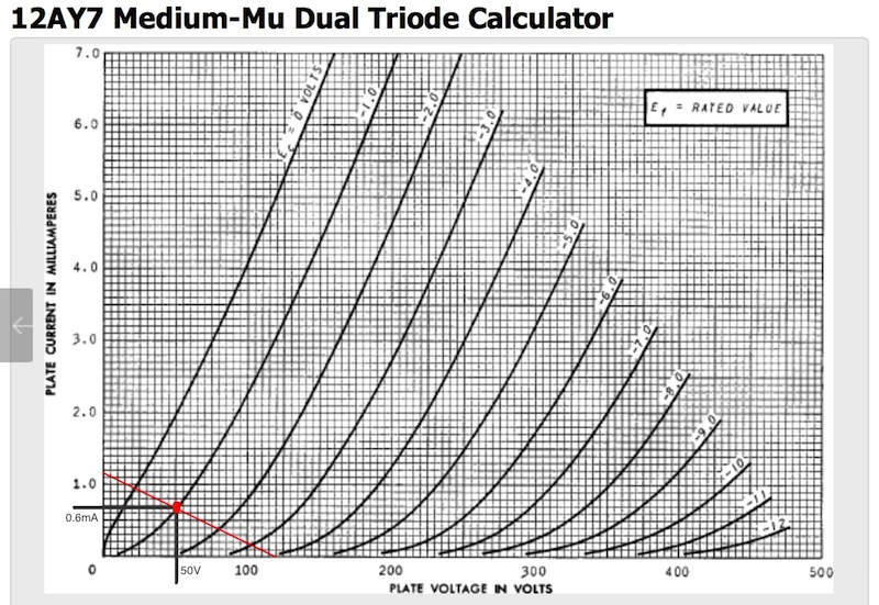
If your plate voltage is that high (and I'll assume that the B+ isn't trimmed back to 130V, since you have 148V on the plate), then there isn't any plate current flowing.  This explains why you cannot trim the B+ low enough.  Since this supply is not regulated (nor is the original) it requires a plate current to flow before it can be trimmed.

First off, the grid voltage doesn't look correct.  Did you remove the short between the bias voltage wire and ground in the stock XLR wire mount inside the mike?  Just like in the PSU, Alctron has a wire whisker bridge from the ground wire over to the pin we use for the P4 right on the XLR jack in the bottom of the microphone itself.  I highly recommend that anyone contemplating building this mike remove all of the stock wiring from the XLR jacks in both the PSU and the mike:  the soldering was suspect from the factory IMHO, and it's better if you put a new wire there yourself with a fresh piece of heat shrink tubing for each (mainly to make sure there are no shorts anywhere) just like Chunger did in the build pics.

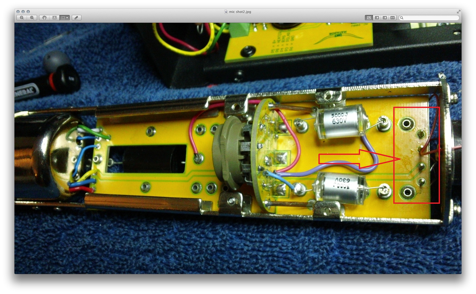
Even if the bias is shorted in the mike:  it doesn't explain the lack of plate current:  even if the grid is grounded, we should be flowing plate->cathode current:  nearly 1mA if the tube datasheet is to be trusted.  Are you sure that the heater is activated?  From your picture, it looks like you are using the "first" side of the tube (connected to TP1, TK1, and TG1).  What is pin4 sitting at (referenced from pin9)?  Is the tube glowing on the inside (may need to be in a dark room to see it)?

The only other explanation is that we have a ground reference problem.  With the mike powered down, set your meter to "low resistance" measuring mode (unless your DVM is auto-ranging), and plug the negative side of your DVM to the ground node in the PSU (labeled P6), or your green wire in the bottom picture.  Connect the 7-pin cable, and put the other side of your DVM on the P6 node in the mike (right above XP2).  You should be reading less than an ohm between these two points.  Then move the DVM over to pin9 on the tube socket, and you again should be reading less than 1 ohm.
 
One piece of advise for everyone 

Speaking of High Impedance Isolation , I would strongly advice everyone going forward to have a special attention to this section in the red rectangle on the board ,
Comments from Matador will only apply if this section of the boards is impecably clean , attention to small details like this one will make this project works like a charm or transformer in a popping-windying Nightmare.

as the first depicted picture in this build thread shows.
Hope this helps everyone.
Best
Dan,

58d0281993bbb.jpg


the reason I avoided re-using the stock bell housing setup in my sample build was to avoid shorts and other hookup problems at the base of the microphone that can result from sloppy soldering and faults in heat shrink tubing installation.  It is impossible to visually inspect for solid wiring once everything is jammed into the bell-housing.

I hope that I placed a strong enough emphasis in the build documentation about keeping the microphone pcb impeccably clean in this build.  Please take the time to scrub the board properly with 90% isopropyl alcohol and make sure all solder flux residue has been cleaned especially in the sections that poctop highlighted.  This is not merely for aesthetics.
 
Ok guys thanx, I new someone was going to flame me for that! ;D i want to say that i have 91% alcohol right in front of me the whole time, and i use it frequently. I noticed the picture showed that flux scale, really hard to see before the pic? it is a testament to how important it is to be clean, and i will have to clean it better for sure, also, i shrink wrapped and very carefully place the wires in the bell housing.

Matador, thanx for the reply, I did have a tube glowing in there nicely(maybe to nicely?), the B+ trimmer is counter clockwise 100% and the 148v reads at psu w/without mic plugged in? I clipped the p4 jumper at all connectors. My next move is to completely strip all the wiring off and start over on it, including the 7 pin mic cable, i will be very slow and deliberate to see if i can catch THE problem

I'll report back when i'm done

thanx a ton for the support fella's! BTW, not too long ago, i would read these threads and think "what the heck is B+ plate v, and grid bias?" now i almost know! lol!;D
T

 
Before you do all of that, let me be more specific:

1) Plug in mike, fire everything up
2) Set DVM to voltage mode
3) Clip the negative/ground lead to the PSU P4 node (in the PSU itself).
4) Measure TP1, TG1, TK1, and heater with the other probe lead - measure right at the tube pins (1, 2, 3, and 4)

Everything must be connected while this is done.
 
Thanx again for the help Matador,

Ok then, Mic plugged in, pin 4 jumper to ground cut everywhere, no tube inserted, power supply on.

Measurements on the tube socket, MM set to dcv
Tp1, tube socket pin1 (B+ plate voltage)=148
Tg1, tube socket pin2 (grid bias)=.032
Tk1, tube socket pin3 (cathode grnd)=grounded
      tube socket pin4 (heater)=6.3volts

This is what i reported early, minus the heater voltage

thanx
T

 
tonycamp said:
Thanx again for the help Matador,

Ok then, Mic plugged in, pin 4 jumper to ground cut everywhere, no tube inserted, power supply on.

Measurements on the tube socket, MM set to dcv
Tp1, tube socket pin1 (B+ plate voltage)=148
Tg1, tube socket pin2 (grid bias)=.032
Tk1, tube socket pin3 (cathode grnd)=grounded
      tube socket pin4 (heater)=6.3volts

This is what i reported early, minus the heater voltage

thanx
T

Just to be clear:  this is all with no tube installed?

What is the grid bias at the PSU (node P4)...is it 0.032V as well (it should be).  Adjusting the 5K resistor R3 does nothing?

If you remove the cable from the PSU, and re-install the 180K resistor between B+ and GND at the XLR output jack, does the bias recover?  Is it then adjustable.

Can you re-install the tube and post the pin 1-4 data again (I assumed all this stuff was with tube installed:  no tube, no plate current).
 
Matador said:
tonycamp said:
Thanx again for the help Matador,

Ok then, Mic plugged in, pin 4 jumper to ground cut everywhere, no tube inserted, power supply on.

Measurements on the tube socket, MM set to dcv
Tp1, tube socket pin1 (B+ plate voltage)=148
Tg1, tube socket pin2 (grid bias)=.032
Tk1, tube socket pin3 (cathode grnd)=grounded
      tube socket pin4 (heater)=6.3volts

This is what i reported early, minus the heater voltage

thanx
T

Just to be clear:  this is all with no tube installed?

What is the grid bias at the PSU (node P4)...is it 0.032V as well (it should be).  Adjusting the 5K resistor R3 does nothing?

If you remove the cable from the PSU, and re-install the 180K resistor between B+ and GND at the XLR output jack, does the bias recover?  Is it then adjustable.

Can you re-install the tube and post the pin 1-4 data again (I assumed all this stuff was with tube installed:  no tube, no plate current).

Yes, all the measurements were taken with NO tube installed, the grid bias trimmer seems to work fine, at p4 on the power supply and at the bottom of the mic pcb wire hookup p4 position, I measure -1v(i adjusted it with the 5k R3 trimmer), but at the tube socket pin 2(grid bias)measures 0.032? this seems wrong to me?

I will put the 182kR across plate to ground, and then I'll put the tube in and report all the measurements at all 4 socket pins, for both.

 
If the p4 node at the bottom of the mike is ok, then it's fine.  You really cannot read the grid directly as the impedance of the meter will demolish the voltage.

Install the tube and report pin 1-4.  I suspect the PSU is fine, and it's something simple.

You are very close!
 
Ok Matador, here we go

At the PSU with a 182k resistor accross pin 1 to grnd 7

P5 B+ reads=                  92v (trimmer is all the way counter clockwise)
P8 heater reads=              6.5v
P4 bias reads=              -1.46v

With the tube in it and glowing

tube socket pin 1(B+) reads=120v                          psu reads=133v(trimmer is 100% counter clockwise)
tube socket pin 2(grid bias) reads=-.653                  psu reads=-1.1
tube socket pin 3(cathode grnd) reads=grnd            psu reads=grnd
tube socket pin 4(heater) reads=6.28                      psu reads=6.51

I did reflow every point on the mic and psu pcb's(after i cleaned them :p), the fact that the resistor load got the B+ down to 92v has to mean the problem is in the mic?

Thanx
T

 
So for some reason, the tube flows only 0.1mA plate current when it should be flowing over 4mA (without considering the dropping across the PSU filters).

Let's eliminate the tube and its biasing from consideration.  Remove the tube, and we'll substitute a fixed "plate resistance" to simulate the tube.  Under normal conditions, we should see about 0.5mA of current with the plate sitting at about 60V, which is a plate resistance of about 120K.

Remove the tube, and solder our virtual plate resistance between pins 1 and 3 of the tube socket.  You can tack it right to the bottom where the solder lugs stick out.  This should simulate the DC conditions of the tube, and you should be able to see pin 1 of the socket sitting at around 50-60V and the B+ at about 92V (with the B+ adjust trimmer 100% fully clockwise).

What tube are you using by the way?
 
In case it is useful, here is a plot for the DC biasing conditions of a 12AY7/6072A tube in the C12 circuit with a 100K plate load resistor:

12ay7_c12_bias.jpg


So you can see with -1V grid bias, we follow the -1V curve down until it intersects the load line, and we have a plate voltage of about 50V at about 0.5mA - 0.6mA plate current (or about 82K to 100K of plate resistance).

You can also see the gain from the curve:  if the grid voltage goes from -1V to -2V (a 1V change), then plate voltage swings from 50V to about 80V, or 30V, for a gain of 30 (or 29.5dB).

Like I stated above to tonycamp, we can use a plate resistor to test the circuit prior to putting in a real tube by inserting a resistance from plate (pin 1) to cathode (pin 3) of 82K to 100K which should simulate the above idling point.
 
Matador said:
So for some reason, the tube flows only 0.1mA plate current when it should be flowing over 4mA (without considering the dropping across the PSU filters).

Let's eliminate the tube and its biasing from consideration.  Remove the tube, and we'll substitute a fixed "plate resistance" to simulate the tube.  Under normal conditions, we should see about 0.5mA of current with the plate sitting at about 60V, which is a plate resistance of about 120K.

Remove the tube, and solder our virtual plate resistance between pins 1 and 3 of the tube socket.  You can tack it right to the bottom where the solder lugs stick out.  This should simulate the DC conditions of the tube, and you should be able to see pin 1 of the socket sitting at around 50-60V and the B+ at about 92V (with the B+ adjust trimmer 100% fully clockwise).

What tube are you using by the way?

Good morning Matador, Great graph! This is like doing a science project in school, except in this case, you actually give a poo! ;D

I've been using the chinese donor Alctron tube, i swapped in a 12ax from my ampeg, to make sure it wasn't a tube issue, but the Alctron tube glows nicely and seems fine for testing purposes(he says with 0 confidence :-\).

To be clear, you want me to pull tube, strap a 128k resistor across tube socket pin 1 to 3?, then measure pin 1 B+v at mic(should be 50-60v), and B+v at PSU should be 92v?

I've been staring at the schemo, trying to understand better? still too much of a newb, but getting better slowly and carefully. I hope all these posts help others, and i'm not just cluttering up the airwaves.

thanx again for your help Matador
T
 
Yes.  You can also try just inserting the resistor
into the socket itself (if the socket is tight enough to hold the resistor leads).

Before that, another easy experiment:  hard short the grid (pin 2).  From the curve above, this should flow 1mA (limited by B+).  If the current shoots up (and B+ drops down from 130) then the problem lies in the grid biasing.
 
Ok done,

B+ trimmer fully counter clockwise, 127k resistor across tube socket pin 1 to 3,
socket pin 1 reads=53v

at the PSU, pin P5 B+ reads=95v

Exactly as you said! what now said the zombie woof?lmao!!! ;D

I picked up a 6072 tube from Christian for this mic, but I dare not put that sucker in till i'm sure i wont fry a c note :eek:
 
Just a thought, tonycamp,

I highly distrust the tubes that come stock on the HT-11A and the 12AX7 is wrong type for the circuit.  I recommend sourcing a known-working, stable, and broken in 6072A or 12AT7 for this build.  If you're already ordering from Christian Whitmore, he  can supply you with a tube at low cost that spec's out for testing, but perhaps is microphonic or otherwise not "mic-grade" but will allow you to test for function and calibrate voltages.


chunger said:
Just a thought, tonycamp,

I highly distrust the tubes that come stock on the HT-11A and the 12AX7 is wrong type for the circuit.  I recommend sourcing a known-working, stable, and broken in 6072A or 12AT7 for this build.  If you're already ordering from Christian Whitmore, he  can supply you with a tube at low cost that spec's out for testing, but perhaps is microphonic or otherwise not "mic-grade" but will allow you to test for function and calibrate voltages.

I was just thinking where can i get another 6072, Christians select 6072 arrived yesterday, i'll have to hit em up for a tester if i cant find one here. I tried to desolder the one out of my mk47 donor i got from you, but petted the bunny on that one George :D
 
Agreed with Chunger:  for some reason this tube is highly suspect.

And don't worry about the questions:  that's what this thread is all about.  All of this troubleshooting applies equally well to any tube circuit:  the tube doesn't know what circuit it's installed in!  I'm sure others will benefit from this:  I had it in the back of mind to make a checklist of tests that people could use in order to make sure everything was working correctly prior to installing the tube.

I would quickly try removing the test resistor, re-installing the tube, and shorting the grid.  You should see a similar collapse of the B+ voltage like the test resistor.  If not, then the tube is highly suspect, as everything else appears as it should be.
 
Matador said:
Agreed with Chunger:  for some reason this tube is highly suspect.

And don't worry about the questions:  that's what this thread is all about.  All of this troubleshooting applies equally well to any tube circuit:  the tube doesn't know what circuit it's installed in!  I'm sure others will benefit from this:  I had it in the back of mind to make a checklist of tests that people could use in order to make sure everything was working correctly prior to installing the tube.

I would quickly try removing the test resistor, re-installing the tube, and shorting the grid.  You should see a similar collapse of the B+ voltage like the test resistor.  If not, then the tube is highly suspect, as everything else appears as it should be.

Ok, Alctron tube back in,
i jumped grid tube socket pin 2 to ground, and got 54v B+ at pin1 on the tube socket and 94v B+ at p5 on the PSU

removed the grid jumper, i get 120v B+ at pin1 tube socket and 130v B+ at p5 on the PSU!......=I'm absolutely positively sure, that all this says bad tube.....maybe i think? ;D

T
 
Back
Top