Official C12 Clone - Build and Support Thread

GroupDIY Audio Forum

Help Support GroupDIY Audio Forum:

This site may earn a commission from merchant affiliate links, including eBay, Amazon, and others.
Interesting.  That actually looks correct.

Let's debug the bias supply next:  try the following in sequence:

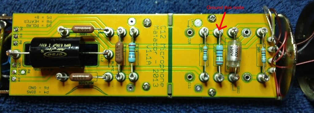
1) Instead of shorting the grid, short the turret where R11, R15, and C10 connect.  This is the node at the turret right "above" the upside-down turret called "CATH".  In your second picture, it is the next turret to the right along the top (you can see that the second, third, and fifth turrets have a link together).

You should observe similar behavior as directly shorting the grid.

2) Lift up C10 on the underside where it connects along the top (next to your purple wire), and remove the short from step 1 above.  See what happens to B+ and plate voltage (pin 1).

Something is odd with one of the three components above (R11, R15, or C10).
 
Ok, sorry for the delay, i had to do a little of this pita thing i call work! ;D I will get on it and report my findings
 
very quickly, i have solid soldering skills and i even use an alligator heat clip on the leads of sensitive caps. do you think a cap went bad?
 
This was the node that should be grounded:

mic2.jpg


You can leave C10 pulled out if you haven't put it back in.

Grounding this node should mimic grounding the grid directly if everything is working properly.

You can also lift the side of C13 that is connected to the turret labeled "grid" and test that config as well.

It looks like there is DC current flowing through the 250M resistor and is messing up the biasing.  Due to the high impedance, even a tiny current can blow up to a significant voltage.  This could be caused by:

1) Leaking C13 which leaks polarization voltage onto the grid
2) Leaking C10 which leaks bias current and causes a drop across R11 which will cut off the tube
3) Bad tube which is leaking grid current, which forms a drop across R15

If you are careful with soldering I am leaning towards #3.
 
Ok, here's the measurement from the turret in your pic,(previously i shorted the one below it ::))

Shorted to ground, My measurements read as follows with tube inserted

at mic tube socket pin 1, plate B+=97v and at the psu 119v
at mic tube socket pin 2 grid bias -0.5v and at the psi -1.131(i noticed the bar meter on my fluke was pulsing a bit?)
at mic tube socket pin 3 grnd grnd
at mic tube socket pin 4 heater 6.3 and 6.5

I hope i did that correctly this time, should i just order those 3 styrenes and replace them? A tester tube is on the way from Christian. I once overed my wiring, looks good, shows good continuity and no shorts between wires on PSU and mic.

thanx again
T
 
This was with C10 removed?

This action is correct:  that means the 250M R15 resistor is probably ok. 

Leave C10 out, then ground the node P4 right as it enters the bottom of the mike.  It should behave the same as above.  This should confirm that R11 is ok (I'm guessing it is...these resistors are tough).

 
Matador said:
This was with C10 removed?

This action is correct:  that means the 250M R15 resistor is probably ok. 

Leave C10 out, then ground the node P4 right as it enters the bottom of the mike.  It should behave the same as above.  This should confirm that R11 is ok (I'm guessing it is...these resistors are tough).

c10 was re installed with a heat dissipator

C5 is correctly oriented in PSU

I will pull c10 and do that test later, unfortunately i'm going to have to work my job till the end of the day, so i'll report it later tonight

thanx M
 
Matador said:
This was with C10 removed?

This action is correct:  that means the 250M R15 resistor is probably ok. 

Leave C10 out, then ground the node P4 right as it enters the bottom of the mike.  It should behave the same as above.  This should confirm that R11 is ok (I'm guessing it is...these resistors are tough).

Ok Matador,

with c10 cap removed, the reading is -1.1v at p4 entering the mic? What do you suggest from here?

thanx
T
 
tonycamp said:
Matador said:
This was with C10 removed?

This action is correct:  that means the 250M R15 resistor is probably ok. 

Leave C10 out, then ground the node P4 right as it enters the bottom of the mike.  It should behave the same as above.  This should confirm that R11 is ok (I'm guessing it is...these resistors are tough).

Ok Matador,

with c10 cap removed, the reading is -1.1v at p4 entering the mic? What do you suggest from here?

thanx
T

First off, measure pins 1-4 with C10 out.

Then measure pins 1-4 again with the P4 node shorted right where it enters the mike.
 
Matador said:
tonycamp said:
Matador said:
This was with C10 removed?

This action is correct:  that means the 250M R15 resistor is probably ok. 

Leave C10 out, then ground the node P4 right as it enters the bottom of the mike.  It should behave the same as above.  This should confirm that R11 is ok (I'm guessing it is...these resistors are tough).

Ok Matador,

with c10 cap removed, the reading is -1.1v at p4 entering the mic? What do you suggest from here?

thanx
T

First off, measure pins 1-4 with C10 out.

Then measure pins 1-4 again with the P4 node shorted right where it enters the mike.

Matador, i was wondering the same thing, am i the only one who's attempted to put this together so far?, or is it so easy that i'm the only jackass who cant get it done? ;D

Both sets are measurements with no C10

tube socket pin 1= 117v at psu 131v
"        "        pin 2= -0.55 at psu 1.1v
"        "        pin 3=grnd grnd
"        "        pin 4=6.3 at psu6.5

with the p4 at the entry of the mic shorted to ground

tube socket pin 1=113v at psu 125v
"      "        pin 2=0.56 at psu .040
"      "        pin 3 grnd grnd
"      "        pin 4=6.3 at psu 6.5

thanx
T
 
Matador said:
Just to ask:  has anyone else got this working successfully?  ;)

I got 1 to work. . . it was a smooth build  8)

Several kits went out to early adopters who have parts in hand, so I'm hoping those folks don't have too long of a build queue, but that's probably wishful thinking.  This is DIY-world after all.
 
You would be shocked at my lack of technical knowledge and the general incompetence displayed behind the scenes at the Chinese Labor Camp.  But, I do think things through quite thoroughly before ever pickup up a soldering iron and make sure:

1.  I won't hurt myself or blow something up
2.  I'm certain each step is correct

With such a severe deficiency in trouble-shooting capability, I need to make EVERY effort to not make a mistake.
 
Hey Chung, right there with you! I'm very careful, and I've been pretty successful with my projects so far, this one is very well put together and should be a piece of cake considering the work you guys put in, it's gonna be something silly in the end, and probably my fault. Thank goodness for matadors cognitive capacity!, otherwise  i'd be adrift, paddle free!

Cant wait to get this girl rollin, thanx again for the project fella's!

T
 
Matador said:
Just to ask:  has anyone else got this working successfully?  ;)

...triplets here:
http://www.groupdiy.com/index.php?topic=51766.0


Attachments

  • IMG_2968.JPG
    IMG_2968.JPG
    171.1 KB · Views: 178

Latest posts

Back
Top