Official C12 Clone - Build and Support Thread

GroupDIY Audio Forum

Help Support GroupDIY Audio Forum:

This site may earn a commission from merchant affiliate links, including eBay, Amazon, and others.
Matador said:
Nice to hear!

Can you define 'very low', and under what conditions (like pattern, etc)?

OK, installed the TC capsule and the 6072A 5-Star from Christian Whitmore. Unfortunately, additionally to the low output, there is a severe noise in the signal. See file in dropbox. It was recorded in cardioid mode at about 15 cm distance through an UA Apollo 8 interface with 65 dB of gain. Such amounts of gain are usually only necessary for Ribbons.
Hope to get some hints once again  :)

https://www.dropbox.com/s/tnj29615bvgyo5i/251_Test01.mp3?dl=0
 
Neutrino said:
OK, installed the TC capsule and the 6072A 5-Star from Christian Whitmore. Unfortunately, additionally to the low output, there is a severe noise in the signal. See file in dropbox. It was recorded in cardioid mode at about 15 cm distance through an UA Apollo 8 interface with 65 dB of gain. Such amounts of gain are usually only necessary for Ribbons.
Hope to get some hints once again  :)

https://www.dropbox.com/s/tnj29615bvgyo5i/251_Test01.mp3?dl=0

Interested in the progress of this too since I have similiar problem with my 251 mod. Not as severe noise though but I have to crank all of my 57db of my clarett 4pre to get a somewhat descent signal... And when I do I’m not sure if its the inherent noise of all that gain or the mic itself thats the problem! But the gain remains very low on mine and my tech has come to a halt without scematics!
 
Try these steps from post #2202:

[quote author=Matador]
Hallo weiss,

Try to narrow down where the noise is coming from.  I posted this several times in the thread, but the basic steps are:

[list type=decimal]
[*]First make sure you have a low impedance ground:  with everything powered off, check the resistance between ground on the PSU PCB and all ground points in the mike body, including all parts of the outside shell.  You should have less than 0.1 ohms everywhere in the mike
[*]Make a small length of wire with two small alligator clips, one on each end
[*]Clip one end to ground on the PCB
[*]Starting at the 'output' hard ground different points in the circuit:  then measure noise:
[/list]
  • the output of the coupling cap (where it enters the transformer) - it should be dead silent
  • the grid of the tube - this should only output the self noise of the tube
  • the capsule connection - this should only be the noise of the tube + HiZ components
You should be able to see the noise contribution of each stage this way.
[/quote]
 
Matador said:
Try these steps from post #2202:

For my understanding: The noise shall be measured at the XLR output of the mic. I.e. if I don't have an oscilloscope, I could as well record the audio in my DAW. Correct?
 
Neutrino said:
For my understanding: The noise shall be measured at the XLR output of the mic. I.e. if I don't have an oscilloscope, I could as well record the audio in my DAW. Correct?

Correct: all of these tests happen inside the mike body, and you can just record 'silence' in your DAW.

Keep in mind, after each test, you need to re-install the microphone body and screw it tight, otherwise all you'll record is 50/60Hz hum. :)
 
Matador said:
Correct: all of these tests happen inside the mike body, and you can just record 'silence' in your DAW.

Keep in mind, after each test, you need to re-install the microphone body and screw it tight, otherwise all you'll record is 50/60Hz hum. :)

OK, I got it figured out. I had the reversed the primary and secondary of the output transformer (Haufe T14/1)  :eek:, which explains both the low output and the high noise to me (due to high output impedance?)

Cardioid mode seems to work normally now and without any audible noise. However, the pattern switch doesn't seem to be doing what it is supposed to do  :-[. The mic doesn't pick up sound from the rear diaphragm  neither in figure-8 nor omni mode.

I checked the voltages at the POL terminal on the mic:
omni: 0 V
cardioid: 50.8 V
figure-8: 108.7 V
Seems about right, doesn't it? Capsule connections als seem to be good
 

Attachments

  • IMG_3808.jpg
    IMG_3808.jpg
    113.4 KB · Views: 63
Neutrino said:
Cardioid mode seems to work normally now and without any audible noise. However, the pattern switch doesn't seem to be doing what it is supposed to do  :-[. The mic doesn't pick up sound from the rear diaphragm  neither in figure-8 nor omni mode.

This sounds similar to a problem I encountered with my first D12 build. Everything was working great in cardioid, but I couldn't get other patterns working. I looked everywhere on the mic for a couple weeks and finally spotted that hidden, really hidden on the power supply 7 pin jack between the shrink wrapped connectors, was a wire connecting the ground to Pin 7 and then, also Pin 4. It was one of the Alctron power supplies, so if you are using a similar Chinese power supply, you may want to look for it.

Once I removed the ground from pin 4, all the issues I was having, including the voltage drain on cardioid to Fig 8 side of the selector and the low polarization pattern voltage all went away. The mic worked perfectly after that.
 
Also make sure you are getting a good connection to the rear membrane and backplate. Sometimes the heat from soldering can loosen the connections. Check that the screws are snug. For the backplate there are 2 connections so you can at least check for continuity between them to see if you've got a connection there.
 
Tim Campbell said:
Also make sure you are getting a good connection to the rear membrane and backplate. Sometimes the heat from soldering can loosen the connections. Check that the screws are snug. For the backplate there are 2 connections so you can at least check for continuity between them to see if you've got a connection there.

Thanks Tim,

I finished the second microphone now and tested it with the same PSU. It has the same problem, as the first mic ( only front capsule working).  My conclusion is that

1. either I have a systematic build error in both mics
2. or there is something wrong in the PSU

How can I rule out one of these options to proceed?
 
Hi guys! This is a question about my  251 build that had very low output and some hiss/noise! (Seems like this thread is more active and thats why I post here)

I was asked in another thread to check my resistor values to see if any of those are wrong. When I was checking I found a few things which may need to be changed. I just need to know if you guys think that may be the cause of my low output.  Image attached below!

Firstly the resistor in R14 seems to be 10M instead of 8M and the component under in the same pic has 630V instead of 250v (both 100J) -  are these a probable cause?

Sorry for being such a noob, I’m gonna book a date to fix this with my tech guy and are looking to prepare to get this issue fixed once and for all! :)

Edit: I figured the Polystyrenes voltage don’t matter but still, do you think the 10M where the 8M should be at R14 can matter that much?


Attachments

  • 2D929983-4910-4445-BE38-5E37470867E2.jpeg
    2D929983-4910-4445-BE38-5E37470867E2.jpeg
    603.1 KB · Views: 45
Tim Campbell said:
Also make sure you are getting a good connection to the rear membrane and backplate. Sometimes the heat from soldering can loosen the connections. Check that the screws are snug. For the backplate there are 2 connections so you can at least check for continuity between them to see if you've got a connection there.

That was it! On both mics the rear backplate connection was loose. Now both work fine and sound great. Thanks all of you for your help! Much appreciated!!!
 
ribor92 said:
Hi guys! This is a question about my  251 build that had very low output and some hiss/noise! (Seems like this thread is more active and thats why I post here)

I was asked in another thread to check my resistor values to see if any of those are wrong. When I was checking I found a few things which may need to be changed. I just need to know if you guys think that may be the cause of my low output.  Image attached below!

Firstly the resistor in R14 seems to be 10M instead of 8M and the component under in the same pic has 630V instead of 250v (both 100J) -  are these a probable cause?

Sorry for being such a noob, I’m gonna book a date to fix this with my tech guy and are looking to prepare to get this issue fixed once and for all! :)

Edit: I figured the Polystyrenes voltage don’t matter but still, do you think the 10M where the 8M should be at R14 can matter that much?

The 10M resistor is fine.  I also have that and my mics works fine. The voltage rating on the cap doesn't matter it just means that you have some margin there.

Check once again your trafo wiring. I had the same issue (see a few posts before) and it was simply caused by a reversed primary and secondary. Measure the DC resistances of both windings. The high resistance side goes to the PCB, the low resistance side goes to the XLR output of the mic.
 
Neutrino said:
The 10M resistor is fine.  I also have that and my mics works fine. The voltage rating on the cap doesn't matter it just means that you have some margin there.

Check once again your trafo wiring. I had the same issue (see a few posts before) and it was simply caused by a reversed primary and secondary. Measure the DC resistances of both windings. The high resistance side goes to the PCB, the low resistance side goes to the XLR output of the mic.

Thanks for the tip! My tech and I sat for hours yesterday and checked everything, and all seems correct! It doesn’t even seem to be the microphone emitting noise, it’s very quite. It seems to be my preamp getting noisy at 55 db gain... since the output is so quite..

My tech said that I probably need a preamp that doesn’t get noisy at 50 db + gain becuase the mic is fine. Could that be right? I mean do you guys with c12 or 251 clones have to crank 50-60 db gain to record these mics?

He said something about these mics being 1:1 ratio and therefore not amplifing anything and being pretty quite. But I don’t know if I’m ready to accept that fact as the truth. Appreciate any help!
 
Lower output is normal for multi-pattern mics, but especially with 6072 tubes. ECC81/12AT7's are a bit louder.

Otherwise you need to wire your mic for true-cardioid, like a real 251. Provides a noticeable 4-6dB boost in cardioid.
 
The circuit is not 1:1, it's about 8dB between the preamp (about 30dB of gain) and the output transformer (about -22dB of loss).

'Quiet' is a relative term:  and depends on the kind of source you are recording.  Two C12's used as drum overheads didn't need much gain from the preamp, but recording a quieter source in a larger space might have needed more.

Banzai, what do you mean by 'true cardioid'?  both the 251 and the C12 use 60v as a polarization voltage with the other side grounded (to the side of the capsule facing 'front').  The main difference is in how to treat the rear membrane/backplate, which are floated in the 251 and connected to +60V in the C12.  I don't see how that would account for 4-6dB output difference.
 
Matador said:
Banzai, what do you mean by 'true cardioid'?

Rear diaphragm (and rear backplate, depending on design) completely removed from circuit.

both the 251 and the C12 use 60v as a polarization voltage with the other side grounded (to the side of the capsule facing 'front').

Only C12 has the front diaphragm always connected to ground. No part of a 251 capsule is ever connected to ground, except for the rear backplate in Fig-8. C12 capsule is also polarized through the backplates, 251 through front diaphragm etc.

To me they're very different.

I don't see how that would account for 4-6dB output difference.

Try any true-cardioid mic like a 251, U47, U67, or U87, and they're always louder in cardioid. Something to do with the parallel capacitance of two active diaphragms in multi-pattern mics vs only the one active diaphragm in true-cardioid mics.

But more importantly than a difference in sensitivity, true-cardioid sounds different to a multi-pattern cardioid. However close you try and match the rear diaphragms voltage to the polarization voltage, you won't be able to cancel out its effects completely.
 
Matador said:
The circuit is not 1:1, it's about 8dB between the preamp (about 30dB of gain) and the output transformer (about -22dB of loss).

'Quiet' is a relative term:  and depends on the kind of source you are recording.  Two C12's used as drum overheads didn't need much gain from the preamp, but recording a quieter source in a larger space might have needed more.

Banzai, what do you mean by 'true cardioid'?  both the 251 and the C12 use 60v as a polarization voltage with the other side grounded (to the side of the capsule facing 'front').  The main difference is in how to treat the rear membrane/backplate, which are floated in the 251 and connected to +60V in the C12.  I don't see how that would account for 4-6dB output difference.

Cool, thanks for clarifying! The reason I wonder is becuase I have never ever had to push my other mics that hard, and this being DIY it leads me to wonder if having to push 50db+ gain for normal singing to get somewhere near decent levels is as it should.
So 50db+ for vocals, seems normal?
 
Hi everybody !

I'm about to step up and build myself a c12 !
I have one question regarding the power supply.. In every build guide, you're using the one already in place in the mic psu !
I'd like to build my own power supply in an other case.. But I can't find any toroidal transformer with 200v & 9V..
Do you know where I can find one?
Thanks in advance for your answer
 
Sinkia said:
Do you know where I can find one?
I doubt you'll be able to find one with dual secondaries that at 9VAC and 200VAC.  Any reason to not use the stock transformer?

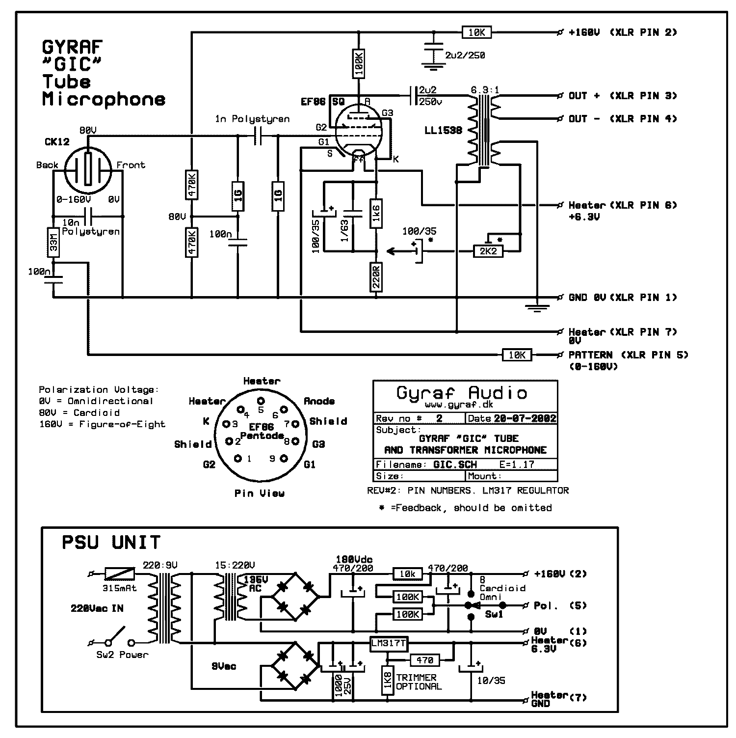
If you are set on toroids, I would use Gyraf's G7 trick of using two 9VAC toroids (like a Triad VPT18-2780):  the first takes the wall voltage (either 115V or 230V) to 9VAC, then, wire a second toroid 'backwards' to go from 9VAC back to 230VAC (standard EU line voltage), which you get by wiring the primaries in series.

gic_s.gif


You'll need to increase R1 and R2 to compensate for 230VAC versus 200VAC.
 
Matador said:
Any reason to not use the stock transformer?

Yeah because I was thinking to buy only the donor body, but not the power supply section, and use an old metal box as power supply


Matador said:
If you are set on toroids, I would use Gyraf's G7 trick of using two 9VAC toroids (like a Triad VPT18-2780):  the first takes the wall voltage (either 115V or 230V) to 9VAC, then, wire a second toroid 'backwards' to go from 9VAC back to 230VAC (standard EU line voltage), which you get by wiring the primaries in series.

You'll need to increase R1 and R2 to compensate for 230VAC versus 200VAC

That's a cool trick ! \o/
Thx !!

I have an other question for you !

what is the difference between the yellow and blue pcb ?

I have seen we can buy the yellow PCB at studio939, and the blue one at vintagemicrophonepcbkit.com

Is there any difference between both ?

Thanks in advance
Adrien
 
Back
Top