


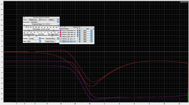
Here's some screen captures taken while looking at a passive Langevin low pass filter under varying load conditions, and some error conditions. Goes to show that with any passive filter, one needs to examine source and load environment to determine whether corrective measures are needed for proper operation.
The Langevin is the same sort of stepped and switchable passive 500/600 ohm LC circuit used by Cinema, Gates, RCA, Altec, UA, Pultec, etc etc. I believe all typically found in America pre-1970 are M-derived filters.
The color code found next to the trace names on the chart let you know what the source and load impedances were for the capture. Example: 540S 560L is 540 source Z and 560 load Z. The load Z is especially critical for overall shape, otherwise it's a wide notch.
Click this link for the full size pic
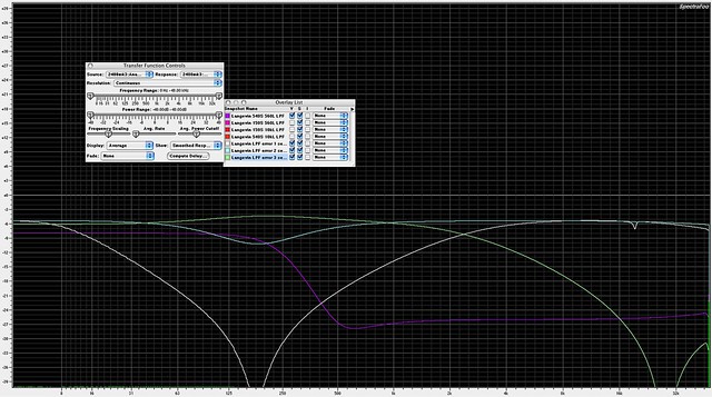
These get really fun. Here I left 'proper' operation in as a purple trace to contrast with some error conditions.
error 1: input and output common connected, output high connected, input high NOT connected
error 2: input and output common connected, input high connected, output high NOT connected
error 3: output common connected, input common NOT connected, input and output high connected
Wildy different curves.
Click this link for the full size pic
The Langevin is the same sort of stepped and switchable passive 500/600 ohm LC circuit used by Cinema, Gates, RCA, Altec, UA, Pultec, etc etc. I believe all typically found in America pre-1970 are M-derived filters.
The color code found next to the trace names on the chart let you know what the source and load impedances were for the capture. Example: 540S 560L is 540 source Z and 560 load Z. The load Z is especially critical for overall shape, otherwise it's a wide notch.
Click this link for the full size pic
These get really fun. Here I left 'proper' operation in as a purple trace to contrast with some error conditions.
error 1: input and output common connected, output high connected, input high NOT connected
error 2: input and output common connected, input high connected, output high NOT connected
error 3: output common connected, input common NOT connected, input and output high connected
Wildy different curves.
Click this link for the full size pic