You are using an out of date browser. It may not display this or other websites correctly.
You should upgrade or use an alternative browser.
You should upgrade or use an alternative browser.
Jensen balanced output
- Thread starter mnats
- Start date


Help Support GroupDIY Audio Forum:
This site may earn a commission from merchant affiliate
links, including eBay, Amazon, and others.
If you think pin 3 is hot and suitable for driving an unbalanced load, you will be disappointed.
If you have to drive a long line from here to Cow Town, the fact that the signal is not really balanced may matter.
Inside the studio, with all proper differential inputs or care taken about unbalanced inputs, it should work fine and avoids a stage.
typing on a new iBook G4: sweet machine but I could not live with this keyboard. Sour grapes because there is no danger anybody will buy me an iBook.
pstamler
Well-known member
Everything PRR said. Also, of course, you'll have 6dB less maximum output. That may or may not matter, depending on the application.
Peace,
Paul
Peace,
Paul
You probably know about this already but just incase or if someone else is searching for different ways to balance outputs and or inputs, Jensen published a paper on it http://www.jensen-transformers.com/an/an003.pdf
Yeah, the Jensen application note mentions how it might have problems driving long lines. Way, way back when I first built my Jensen preamp to use with my portable DAT, I talked to Steve Hogan at Jensen who told me just to ground pin 3. Made sense since the cable runs were so short. But it was interesting to see this new suggestion. I've still got the preamp and have been thinking about "racking" it so this looked like a good idea to me.
The Jensen paper also mentions that this output configuration is truly balanced. So maybe there are two definitions for "balanced"?
The Jensen paper also mentions that this output configuration is truly balanced. So maybe there are two definitions for "balanced"?
[quote author="mnats"]The Jensen paper also mentions that this output configuration is truly balanced. So maybe there are two definitions for "balanced"?[/quote]
As I understand it, it is truly balanced as long as the output impedance of both outputs is the same. The common-mode rejection will still work - it won't if you just ground pin 3.
Best regards,
Mikkel C. Simonsen
As I understand it, it is truly balanced as long as the output impedance of both outputs is the same. The common-mode rejection will still work - it won't if you just ground pin 3.
Best regards,
Mikkel C. Simonsen
SonsOfThunder
Well-known member
[quote author="PRR"]typing on a new iBook G4: sweet machine but I could not live with this keyboard. Sour grapes because there is no danger anybody will buy me an iBook.[/quote] Sorry to hijack, but I think the KB on my new G5 desktop is kinda weird too. I think the keys are spaced a tiny bit wider and I notice I am missing keys a lot!
HTH!
HTH!
> of course, you'll have 6dB less maximum output. That may or may not matter,
True, true. I doubt we often need or want 48V peak-peak signals around the studio, but if you do, then you need two amps push-pulling (or one monster amp...).
And specifically for the 5534: it is rated 44V so according to the factory you could run +/-22V and swing around 36V p-p, not much less than most +/-15V gear in bridge-mode swinging 48V p-p.
Also: IF (big if) you have real 600Ω load and an opamp that will just about drive 600Ω, then push-pulling won't increase the output. With the birdge output each side sees 300Ω. The 5532 is marginal. It does very well in 600Ω, doesn't suck in 300Ω but sure won't swing twice the voltage of one 5532 and one 600Ω load. Go to the wimplier amps like TL072: the '72 will just about not get a hernia in 600Ω (really too low for it) and two half '72s in 600Ω won't make any more level than one side in 600Ω. Of course with more likely 10K loads, this is irrelevant. A '72 is as good as it gets above 2K or 3K so the 5K loading in the bridge is "light" and they will swing 48V p-p. OTOH some of the guys here dredge up old 600Ω passive EQs and high-ratio transformers and really do see 600Ω loads.
I'm about at the point where everything is 5.6V p-p and nothing less than 10K. My one exception is a long transformer-coupled line working about 5V p-p at nominal 150Ω. And for other reasons, that should really be on a dedicated driver. (It feeds "strange" loads, and I don't want their problems coming back to my system.) That run crosses a building power-ground break, volts of common-mode, yet the far end is clean.
> The Jensen paper also mentions that this output configuration is truly balanced. So maybe there are two definitions for "balanced"?
Oh, bosh. They split a hair and decide which side of the split they want to stand on.
In my world, balanced means BOTH balanced signals and balanced impedances.
That plan is balanced impedances. Whatever crap is inducted into the line is absorbed equally, so the differential input on the far end can subtract the crap and end up with just signal. Good.
But there are reasons to drive a balanced signal. If you have hot output lines next to high gain input lines, a balanced signal has zero radiation, the plan you show will radiate just like an unbalanced line. Assuming decent shielding, you need 40dB or 60dB of gain between to get "in trouble", though there may be faint crosstalk or near-instability at lower gains. Yes, in Real Studios we segregated lines every 30dB: mike-lines in one bundle and bay, lines in another, speaker lines somewhere else. But the old Standards are now forgotten, anyway sometimes you want to use the handy line instead of running another snake or pulling a separate bundle.
Balanced also means you can always take an unbalanced input from either pin 2 or pin 3 to pin 1, at 6db less level. With the above plan, pin 2 is full level, pin 3 is "dead". I've lived long enough to remember when pin 3 was often assumed "hot", and probably still have 3-hot baluns in my kit.
Floating means that the radiated field will tend to be zero, self-adapting to some impedance unbalance, and that you can connect it either balanced or unbalanced (or in series with other floating putputs for hasty mixing), or that you can send it to a place with a very different ground (remote recording van, radio transmitter, the far end of my concert hall). Floating is natural in transformers. There are electronic schemes that show nearly the same behavior on the bench, though I mistrust them in Real World, and they can't handle more than a few volts of ground difference (transformers take hundreds of volts ground difference).
One great thing about floating outputs: you can run them into an UNbalanced input and get some common-mode rejection. I have an elderly DBX limiter with a wacky output that, while not truly floating, is close enough that it does give nice CMRR into my unbalanced distribution bus.
dpaton
Well-known member
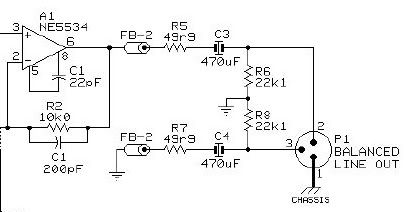
The Jensen circuit shown is an example of the new breed of "impedance balanced" or "ground compensated" connections that are popping up all over.
Like PRR said, they're NOT balanced in any practical way. They ARE impedance balanced at DC, and that's what the marketing folks have latched onto. They're not the kiss of death as line inputs, although I greatly prefer a true balanced input stage.
As outputs I damn them to the deepest, darkest, most fiery pits of HELL. Several companies are cheating, and making the outputs real live +4 (!!!), by bumping the output on pin 2 +6dB to compensate for the loss of the 'cold' output (pin 3), making your indicated +4 a +10 in reality, but only on one side of the XLR, which makes gain structure a pain.
If you're driving a pin-3 hot device, you'll have problems.
If you're driving an impedance-balanced input, you end up with an unbalanced connection, which defeats the putpose of a 3 pin output in the first place.
In short, I hate them.
Soundcraft put them on every XLR and TRS input and output of the GB series, and I had some very cross words with them regarding their advertising, and their response to an innocent question about fitting balancing amps for the main and matrix outs. It made it to the National Sales manager before I gave up. Oy.
In conclusion: Avoid them if humanly possible. Please, for the love of all that is quiet and balanced and transformer coupled. Please?
-dave
Are the impedances not balanced throughout the audio band (and beyond)? My understanding is that they are since the closed loop output impedance of the opamp is "negligible", according Jensen application note.They ARE impedance balanced at DC
Can you post an example of an input circuit using this principle? The Jensen paper only shows an output circuit. All the input circuits in their examples are either transformer balanced or differential amps.They're not the kiss of death as line inputs
What I got from Jensen, PRR and other's posts is that the circuit will "work" provided pin 2 is hot but isn't optimum. If pin 3 is hot you only have to swap two wires. But what is curious is that if you could somehow use this scheme throughout your studio wiring, you'd have lines radiating like mad yet all would be cancelled out at the input end!
Funny that Jensen would suggest a circuit like this that uses <$2 worth of extra parts when they could easily try to sell you an output transformer.
dpaton
Well-known member
[quote author="mnats"]Are the impedances not balanced throughout the audio band (and beyond)? My understanding is that they are since the closed loop output impedance of the opamp is "negligible", according Jensen application note.[/quote]
The math says it is, but my experience says that when you pump large waves of high frequency AC (10KHz at +4) things do not behave ideally. I've run into problems with them in clubs that have noisy environments, installs with shaky power, etc.
It will work, but it won't work well, and at best, it's a compromise.
As an electrical engineer, the idea of selling an unbalanced connection as balanced irks me to the core, and the implementation, tho workable, still leaves me with a bad taste in my mouth, despite the cost advanatages.
-dave
The math says it is, but my experience says that when you pump large waves of high frequency AC (10KHz at +4) things do not behave ideally. I've run into problems with them in clubs that have noisy environments, installs with shaky power, etc.
I don't have a picture handy, but basically you put a resistor from pin 3 to ground, with the value the same as Ri on the op amp buffer that is connected to pin 2. Pretty simple really.Can you post an example of an input circuit using this principle? The Jensen paper only shows an output circuit. All the input circuits in their examples are either transformer balanced or differential amps.
The pin-2/3 thing is fine and good in a fixed install, but in a live or combat audio situation, it's a problem. I'd NEVER use this in my studio. I have too much gear that has transformer inputs, or the oddball DBX quasi-floating inputs that PRR mentioned, to have it work reliably for me. I actually had to either banish or balance all of my unbalanced gear, mainly due to the proximity of a 50KW+ AM broadcast tower (WGN...4.02 miles away). Anything that had unblanced or IB connections picked up the station, right through the half-mile of Neglex that connects everything.What I got from Jensen, PRR and other's posts is that the circuit will "work" provided pin 2 is hot but isn't optimum. If pin 3 is hot you only have to swap two wires. But what is curious is that if you could somehow use this scheme throughout your studio wiring, you'd have lines radiating like mad yet all would be cancelled out at the input end!
It will work, but it won't work well, and at best, it's a compromise.
As an electrical engineer, the idea of selling an unbalanced connection as balanced irks me to the core, and the implementation, tho workable, still leaves me with a bad taste in my mouth, despite the cost advanatages.
Well, there are so many other circuits on their site that have big $$ trannys in them I have a hunch they're not worried.Funny that Jensen would suggest a circuit like this that uses <$2 worth of extra parts when they could easily try to sell you an output transformer.
-dave
[quote author="dpaton"]
As outputs I damn them to the deepest, darkest, most fiery pits of HELL. Several companies are cheating, and making the outputs real live +4 (!!!), by bumping the output on pin 2 +6dB to compensate for the loss of the 'cold' output (pin 3), making your indicated +4 a +10 in reality, but only on one side of the XLR, which makes gain structure a pain.
If you're driving a pin-3 hot device, you'll have problems.
If you're driving an impedance-balanced input, you end up with an unbalanced connection, which defeats the putpose of a 3 pin output in the first place.[/quote]
What console did you encounter that meaures +10 when the output reads +4? I have never encountererd this as it would be silly for them to do so, eliminating headroom (relative to the metering) quickly. Mackies use this output and all soundcrafts with this I have used measure the correct output voltage as indicated by the metering. +4 dbu is 1.228 volts down one line or .614 down 2, but the input amp will subtract the difference and yeld the same results. So technically it is not +10, just +4 delivered two different ways.
As far as defeating the purpose of 3 pin connections, I don't believe in the scenario you describe does so. You lose the ability to drive greater levels with the loss of pin 3 signal but the pin 3 run still gets the noise that 2 does and therefore is subtracted at the input. Tieing pin 3 to 1 does eliminate the 3 pin advantage though.
According to the ieee definition of a balance system both pins must be driven so it is improperly marketed (technically) as you stated.
Brian
mike_relay
Well-known member
I've been doing some reading on balanced and unbalanced connections, as I just got a Tascam TRS-8 and it has only unbalanced RCA ins and outs.
I'm trying to figure out if I should build something to turn these RCAs into balanced XRL or TRS. Reading the Jensen PDF mentioned above.. could I just build something with 2 opamps (the one labeled Typical Balanced Output) for the output and then something like the Typ "Pro" Input circuit to connect to the inputs of the Tascam?
I would really appreciate any comments or any links to more information would be greatly appreciated.
- mike
Here are the specs for the Tascam:
Line Input(unbalanced)
Input Impedance 10 kOhms
Nominal Input Level -10 dBV(0.316 V)
Maximum Input Level +18 dBV(8.0 V)
Line Output(unbalanced)
Input Impedance 10 kOhms
Min. Load Impedance 2 kOhms
Nominal Load Impedance 10 kOhms
Nominal Output Level -10 dBV(0.316 V)
Maximum Output Level +18 dBV(8.0 V)
[quote author="PRR"]One great thing about floating outputs: you can run them into an UNbalanced input and get some common-mode rejection. I have an elderly DBX limiter with a wacky output that, while not truly floating, is close enough that it does give nice CMRR into my unbalanced distribution bus.[/quote]
Great summary on different things that come under the name "balanced"!
At the moment, I'm looking around for a 8in/8out PCI soundcard which will replace my good old (but broken again) 8-track reel-to-reel.
Problem is, my mixer has only unbalanced (RCA) connections for the tape machine, and I fear ground loop problems when connecting to the computer.
Now it's no problem to interface unbalanced out with balanced in (mixer to soundcard), but "balanced" out to unbalanced in (soundcard to mixer) will only work as intended (breaking the GND loop) if the soundcard's output is truely, i.e. *floating* balanced.
As PRR has just explained the difference in-depth, I'll ask my practical question within this thread. Does anybody know if 8in/8out soundcards in the $500.00 range have floating balanced outputs?
In particular, I'm interested in the M-Audio 1010 and the Echo Layla G3.
(Of course I don't expect transformers in there, but that cross-coupled opamp circuit which emulates a floating secondary within a reasonable CM range will certainly do.)
Because, if I don't get this true balanced output operation, I'd better buy an unbalanced soundcard and spend the rest of the money on transformers ...
JH.
Similar threads
- Replies
- 20
- Views
- 926