helios preamp pcb's [boards now available]

GroupDIY Audio Forum

Help Support GroupDIY Audio Forum:

This site may earn a commission from merchant affiliate links, including eBay, Amazon, and others.

mus1k_freak

Well-known member
Joined
Dec 13, 2009
Messages
156
Location
Philadelphia PA
I'm going to keep a list of anyone interested in pcbs, check the first post of page 3 for more info, pm me with how many you want and ill add you to the list, once payment is sent ill mark ya paid so I can get these out as soon as possible once the come in, BOM, mouser cart link, and build guide will be provided for each board, $10 per board $3 shipping in the USA and $7 outside

Mus1k_Freak - 4 boards
Hitchhiker  -  2 boards
Mjrippe -  1 board paid*
AudioHammer - 2 boards
skidmorebay  - 4 boards

Mouser Cart: http://www.mouser.com/ProjectManager/ProjectDetail.aspx?AccessID=3772d0feb8


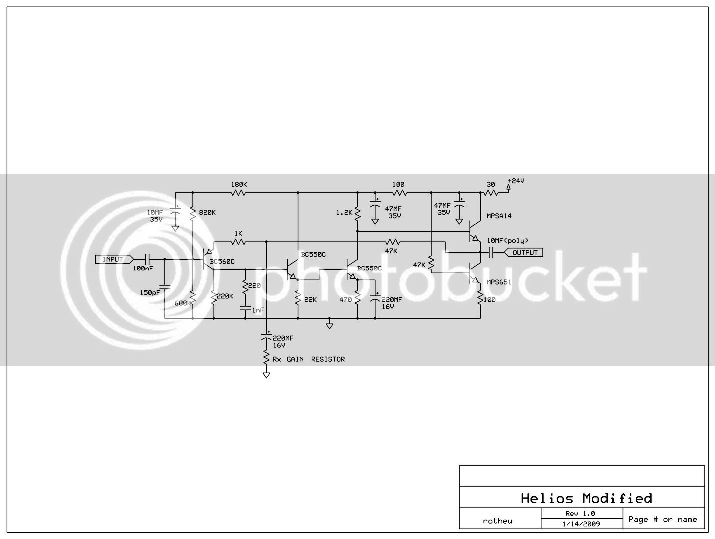
Ive been fascinated with the helios pre amps for awhile, i was thinking about putting together a pcb for just the pre amp section, without the eq (since theres a few of those projects around here already) maybe even make it a 500 series card. this is the schematic was going to use, is there anything that should be  changed before i start inputing it into eagle? ill make provisions for a input and out put transformer, and have it run off 24+ and 0. is there anything else i should know?

index.php
 
You will have to add an output buffer of some kind to drive a output transformer. Google for some solutions...
I grab a couple of PCB if you get it rolling.
 
It is quite a simple circuit. I would have though with using radial leaded capacitors you could make it on quite a small plug in PCB similar to a DOA.

it has no driving capability and Helios had a more complex circuit for that  purpose which you might also usefully create a PCB for.

Attached picture shows originals of both types.

Cheers

Ian
 

Attachments

  • f_DSC00093i_a351m_8dec8e8e.jpg
    f_DSC00093i_a351m_8dec8e8e.jpg
    53 KB · Views: 340
Thats awesome a great reference, thanks! would you happen to have the schematic for the other board? i did a quick search but couldnt come up with anything.


i saw this, which looks like the first one with a buffer on the end

HeliosMod.jpg
 
mus1k_freak said:
Thats awesome a great reference, thanks! would you happen to have the schematic for the other board? i did a quick search but couldnt come up with anything.

I think I have it somewhere on my hard drive. I think it is a little more complex than the one you posted.

Cheers

Ian
 
I I started laying out the above circuit in Eagle,  the line amp seems to be the most popular Helios module,  it's what they used after the eq and inserts in the board for gain make up.  I'm gonna add the  buffer on the end which should drive a 1:1 output transformer if you want to use iron,  I'm also including a ne5532 unbalanced to balanced circuit if you want to save  money and go that route.  You could also run an unbalanced out so  have several options depending on your application. I'll try to get a rough schematic up tonight or tomorrow
 
Here is the schematic of the Helios high level line amp. it is known as the 22113.

Cheers

Ian
 

Attachments

  • helios_hilevel_linecard.jpg
    helios_hilevel_linecard.jpg
    345.1 KB · Views: 422
awesome thank you guys so much! looks like ive got alot to work with now, ill see if i cant get something drawn up as a rough draft, im sure ill have a few questions along the way. any interest in pcb's if i do get this printed up?
 
ruffrecords said:
I did a search for Helios 22113 and came acros this interesting snippet:

http://repforums.prosoundweb.com/index.php?topic=17863.1985;wap2

Cheers

Ian


very interesting! thanks Ian, a cool read for sure  8)

heres my first draft of the schematic, how does it look? are there any obvious errors?

this is assuming the input transformer is wired off the board, and the in+ and in- would be from the transformer out

1556368_10151875062335946_85672313_o.jpg
 
I've tested that circuit and it is not happy driving an output transformer.

Include the added 1 Tr buffer that is drawn in the 2128 line amp that I posted last post and the preamp can drive a transformer. Try bread boarding both and compare. The 3 Tr circuit you post sounds good unbalanced into high loads.

cheers,
Lance
 
All three circuits are very similar, the big difference seems to be whether or not you use a buffer and how the buffer is set up, in the original consoles it looks like they had a single transistor buffer for the out. I think with a few extra pads on the PCB I could build either version, I don't plan on using any transformer on the out either just unbalanced or through a tl072 balancing circuit kind of like the ssl9k pre uses. Small enough that I could rack up 4 channels in a 1u case . The bc550 are the more modern version but any equivalent transistor could be used with a few tweaks for the bias
 
hitchhiker said:
BTW I tried out the first schematic you found with the buffer added on by one of our members and with all due respect I was not taken by my subjective audition. YMMV

ok i edited my original to copy the output of the schematic you posted, which seems to be the correct one, i know alot of the original helios had just the single transistor on the output amp, heres my schematic, hows it look, do i have the output in the correct place?

1656127_10151878347985946_337301927_n.jpg
 
I'm sure others can answer better then me,  the Helios is mainly set up for a 1:1 output transformer for balancing the signal,  should also sound good with just a unbalanced out (save some $$)  I don't know much about quad 8 stuff but the designs look similar,  I'll be getting a  bunch of these made once I finalize the design if anyone wants to try it,  if if there's enough interest I'll do a quad 8 board next  :)


CJ said:
how does that Helios preamp compare to the Quad 8?

what is the ratio of the output xfmr?

thanks!
 
after many revisions, adding features and taking away things, trying to keep it a simple good sounding pre close to the original specs i finally got it down to a design i liked, just ordered some pcb's for a trial run to see how they sound, hopefully get some guys on here to build and test a few and see what they think as well. perhaps if it ends up being a well liked design ill go ahead and put together a 500 series kit with all the bells and whistles i left out of this one  8) ill keep everyone posted, pcbs should be in, in two weeks or so
 
Which Q8 amps are these similar to? I looked at some schematics but the stuff I have (CA127, for example) looks like an opamp to me. 

Is there info on the input transformers for these (ratio/size/etc)?  Their -20 input is not a pad, but using the center tap of the input trafo secondary which I think is pretty cool. But does that imply a 1:10+10 input trafo? 


EDIT: found some info on sowter's site... their 7490 is supposed to be a replacement for the original and is 1:10 with a 1:1 tap...
 

Latest posts

Back
Top