


Matador
Well-known member
This is a feeler thread for a new universal PSU enclosure for tube microphone projects. In reality, it is a triple-rail PSU that is also suitable for tube preamp projects as well.
This PSU board is designed to make use of the stock Alctron dual-secondary supply, which has a 9.5VAC tap and a 200VAC tap. However I think there are some more custom winds in the works, and I think some of the small Triad Magnetics torroids might fit in the stock PSU as well. If you are placing this in your own case then the sky is the limit.
Supply 1 - Heater Supply
Designed to adjust between 4.7V and about 13V. The maximum is really limited by the 9.5V AC secondaries of the stock Alctron transformer, so if you plan on reusing it it will only do parallel heaters. I did manage to sustain over 700mA load so this shouldn't be an issue. Those wanting to do series heaters will need to find a different transformer, as the 9.5V secondaries won't supply enough headroom to the regulator to put out the required 12.6V after regulation. If you supply a separate torroid for the heater supply then you will be fine with regulating up to 12.6V. There is enough heatsink capacity to squeeze 4, 350mA heaters in parallel if you wanted to try powering a dual-tube preamp with it.
This heater supply is fully isolated from ground: hence you can do positive or negative heater supplies by tying one of either sides of H+ or H- to ground. For stock positive supplies you tie H- to ground, and for negative you tie H+. This makes this compatible with U47-like projects, or hybrid projects that use a negative heater to generate the grid bias voltage.
Supply 2 - Bias Supply
This is cap coupled from the heater AC supply so it is fully isolated as well. It is adjustable from 0V down to -2.5V. If you want more negative adjustment range it's a simple resistor change. I managed to pull over 10mA from this supply so it is more than enough for bias duties. Unlike the stock C12 design, this one is fully regulated, so it is a true fixed bias supply.
Supply 3 - B+ Supply
The design is meant to be adjustable from approximately 70V up to about 200V with the stock BOM, which should be good to cover most tube microphone duties. The range can be biased upward with a single resistor change (for perhaps a range of 120V to 250V for tube preamp duty).
I'm not sure of the VA spec of the 200V secondary on the Alctron PSU, but I would guess this should be good to about 50mA or so (which is about 10VA), which is enough to drive quite a few tube gain stages, even for higher current tubes like 12AT7's. I wanted this to also be compatible with stock CCDA microphone stages so this should be plenty for that purpose.
This B+ supply is also fully regulated, so once set for a target voltage it should stick even with tube swaps. The supply is also floating as well, which means you could implement a negative B+ supply (for whatever reason).
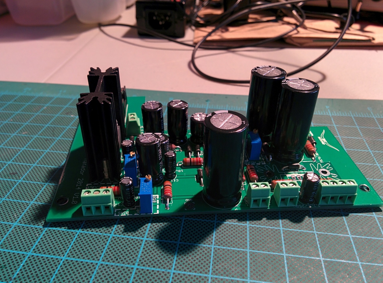
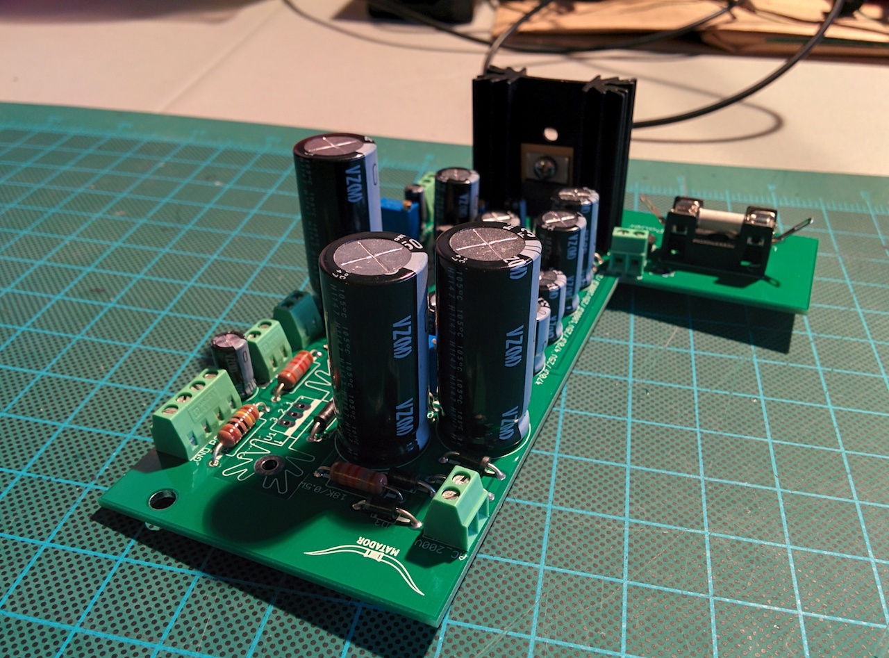
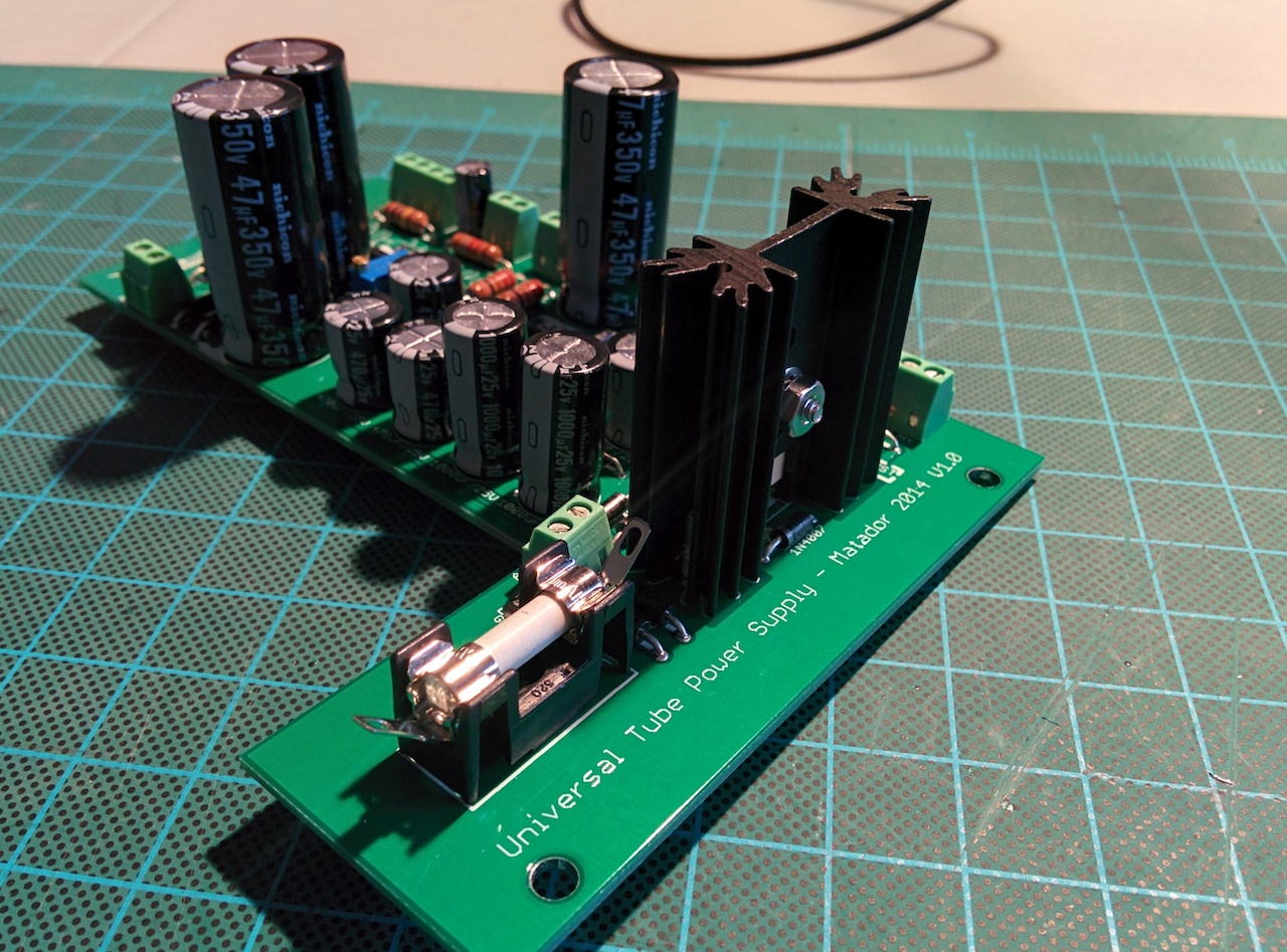
Pics
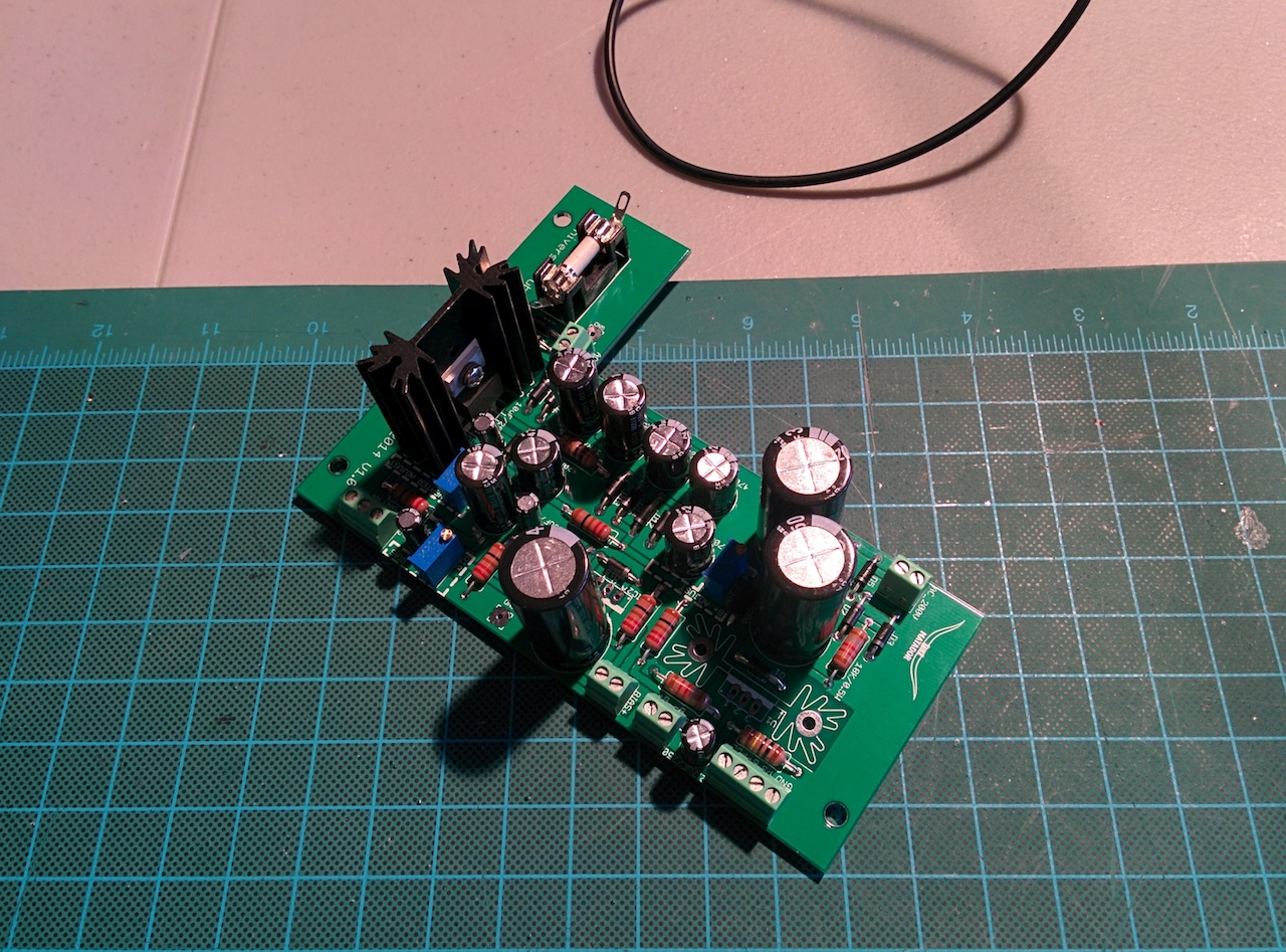
The polarity of the various supplies is decided right at the wire headers: you can bridge a short wire-lead jumper from various ground points to make supplies positive or negative. I'll be testing the prototype with a standard C12 design, which means positive heaters.
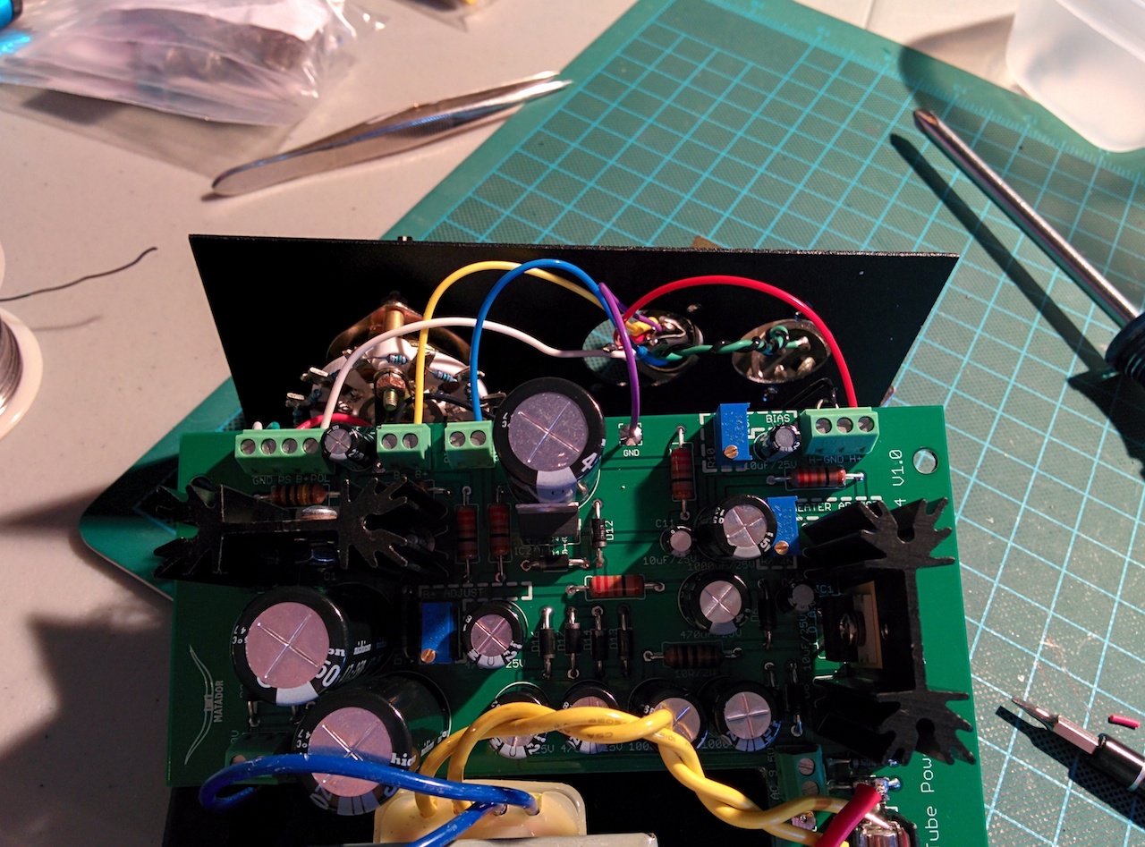
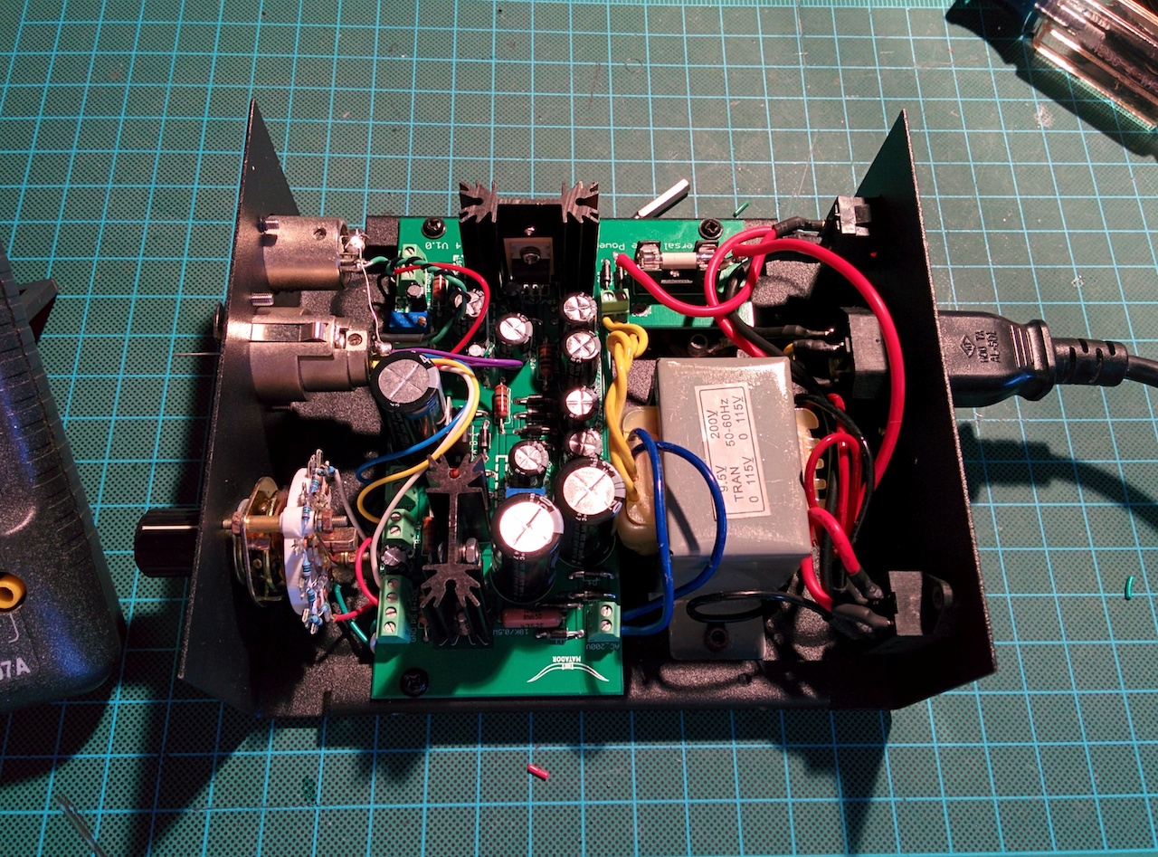
Testing on the first prototype has been positive: essentially every works properly. I have some BOM and layout tweaks to make it perfect though, and once I have that done I'll post the details.
Of course I'll recommend my current winning BOM formula, which is Nichicon high-temp VZ electrolytic caps, Vishay CCF60 2W flame-proof metal film resistors, Bournes sealed multi-turn trimmer pots, and Phoenix connector blocks.
To gauge interest, please post here to the thread with any questions or if you are interested in this project prior to the first board run so we can understand the quantities. My thought had been that it would be available as a separate project, and I believe that Chunger is in the process of obtaining loose PSU's to support them being built stand-alone (but don't quote me until I can confirm).
This PSU board is designed to make use of the stock Alctron dual-secondary supply, which has a 9.5VAC tap and a 200VAC tap. However I think there are some more custom winds in the works, and I think some of the small Triad Magnetics torroids might fit in the stock PSU as well. If you are placing this in your own case then the sky is the limit.
Supply 1 - Heater Supply
Designed to adjust between 4.7V and about 13V. The maximum is really limited by the 9.5V AC secondaries of the stock Alctron transformer, so if you plan on reusing it it will only do parallel heaters. I did manage to sustain over 700mA load so this shouldn't be an issue. Those wanting to do series heaters will need to find a different transformer, as the 9.5V secondaries won't supply enough headroom to the regulator to put out the required 12.6V after regulation. If you supply a separate torroid for the heater supply then you will be fine with regulating up to 12.6V. There is enough heatsink capacity to squeeze 4, 350mA heaters in parallel if you wanted to try powering a dual-tube preamp with it.
This heater supply is fully isolated from ground: hence you can do positive or negative heater supplies by tying one of either sides of H+ or H- to ground. For stock positive supplies you tie H- to ground, and for negative you tie H+. This makes this compatible with U47-like projects, or hybrid projects that use a negative heater to generate the grid bias voltage.
Supply 2 - Bias Supply
This is cap coupled from the heater AC supply so it is fully isolated as well. It is adjustable from 0V down to -2.5V. If you want more negative adjustment range it's a simple resistor change. I managed to pull over 10mA from this supply so it is more than enough for bias duties. Unlike the stock C12 design, this one is fully regulated, so it is a true fixed bias supply.
Supply 3 - B+ Supply
The design is meant to be adjustable from approximately 70V up to about 200V with the stock BOM, which should be good to cover most tube microphone duties. The range can be biased upward with a single resistor change (for perhaps a range of 120V to 250V for tube preamp duty).
I'm not sure of the VA spec of the 200V secondary on the Alctron PSU, but I would guess this should be good to about 50mA or so (which is about 10VA), which is enough to drive quite a few tube gain stages, even for higher current tubes like 12AT7's. I wanted this to also be compatible with stock CCDA microphone stages so this should be plenty for that purpose.
This B+ supply is also fully regulated, so once set for a target voltage it should stick even with tube swaps. The supply is also floating as well, which means you could implement a negative B+ supply (for whatever reason).
Pics
The polarity of the various supplies is decided right at the wire headers: you can bridge a short wire-lead jumper from various ground points to make supplies positive or negative. I'll be testing the prototype with a standard C12 design, which means positive heaters.
Testing on the first prototype has been positive: essentially every works properly. I have some BOM and layout tweaks to make it perfect though, and once I have that done I'll post the details.
Of course I'll recommend my current winning BOM formula, which is Nichicon high-temp VZ electrolytic caps, Vishay CCF60 2W flame-proof metal film resistors, Bournes sealed multi-turn trimmer pots, and Phoenix connector blocks.
To gauge interest, please post here to the thread with any questions or if you are interested in this project prior to the first board run so we can understand the quantities. My thought had been that it would be available as a separate project, and I believe that Chunger is in the process of obtaining loose PSU's to support them being built stand-alone (but don't quote me until I can confirm).
")
