Audio peak limiter for home-brew headphone amp

GroupDIY Audio Forum

Help Support GroupDIY Audio Forum:

This site may earn a commission from merchant affiliate links, including eBay, Amazon, and others.
joaquins said:
Fastest options, diode clipping, very efficient to limit peaks, RMS another story. Another option is to limit the rails of the amp and add a resistor at the output so certain max power could be delivered from the amp to the HP.

If you want a real limiter you may go for a FET or any other simple topology, Fet being the option 1, diode bridge and transconductance after I guess.

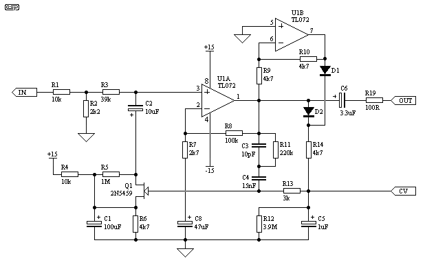
For FET:
1 Fet per channel, some caps and resistors for polarization and an opamp with a couple of diodes for control voltage.
Fast%20Audio%20Peak%20Limiter.gif


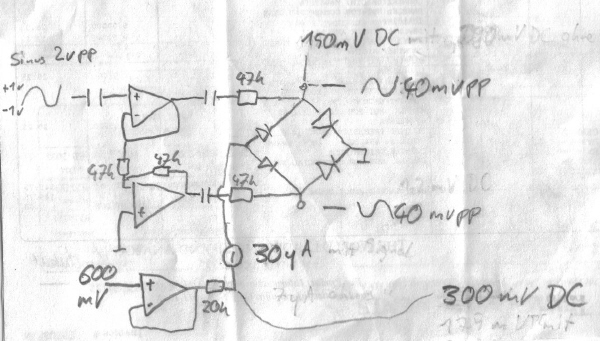
For diode bridge:
4 diodes per channel, one resistor, same for CV.
34046d1176462389-diode-vca-built-measured-what-output-amp-best-diodevca-messung.jpg


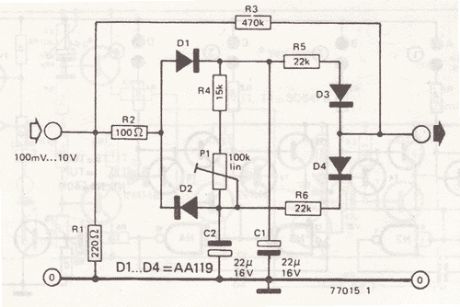
A passive diode, nasty but working (tried out by myself, it could add attack release, ratio and even do asymmetrical compression)
s2012101015058572.gif


For transconductance:
3 transistors per channel, some resistors, same CV.
vca3_667.png


A CA3080 or LM13700 also use this topology but already solved in an IC.

Times could be fixed for fast attack and release for taste.

/*images are for reference of the topology, not the final design that you should use, just to explain my self better, as amp you probably could use the one you already have 2nd and 4th scheme doesn't have the CV generator (rectifier and time constants)*/

JS
Hi js.
How to add attack and release for the passive diode design ?
Thanks
 
Here is a basic simple limiter that can be added to almost any amplifier circuit. The 20k pot make it simple to set the amount of clipping and then final resistors can be used for completed circuits.

Duke
 

Attachments

  • img032.pdf
    303 KB · Views: 77
Audio1Man said:
Here is a basic simple limiter that can be added to almost any amplifier circuit. The 20k pot make it simple to set the amount of clipping and then final resistors can be used for completed circuits.

Duke
Do you think that the fully passive diode limiter will be non usable ?
 
JohnRoberts said:
While it is not exactly like I would do it, it looks like it "should" work. One obscure aspect of that design is that the source of the JFET is biased up to about +5V DC (10k and 4.7k divider).  On Rod Elliot's version there is an * on the 4.7k R6 suggesting you can tweak that value to change the limiting threshold. According to the JFET data sheet the cut-off voltage for 5457 is between -0.5V and -6V. Since that schematic starts with a nominal -5V on the gate, a 6V part would never cut off. Of course the threshold could vary that same several volt range from device to device...
I was just reading this because I was thinking about building the ESP/Phil Alison FET Limiter. It works fine and sounds pretty cool, btw. I just had a question about the time constants. The attack time is claimed to be ~5ms and the release is ~1 second. With the values in the schematic, that's indeed what you get. Using the RC charging formula, 4k7 * 1uF = 4.7ms. However, 3.9M * 1uF = closer to 4 seconds. Obviously there is some other way to determine this. Just curious if someone could shed some light on what that is. The author did state that he moved the resistor that governs the release time up to where the diodes connect in order to allow for faster release times, if required. Is this why the RC formula doesn't work out in reality?

Thanks,
-Aaron
 
absrec said:
I was just reading this because I was thinking about building the ESP/Phil Alison FET Limiter. It works fine and sounds pretty cool, btw. I just had a question about the time constants. The attack time is claimed to be ~5ms and the release is ~1 second. With the values in the schematic, that's indeed what you get. Using the RC charging formula, 4k7 * 1uF = 4.7ms. However, 3.9M * 1uF = closer to 4 seconds. Obviously there is some other way to determine this. Just curious if someone could shed some light on what that is. The author did state that he moved the resistor that governs the release time up to where the diodes connect in order to allow for faster release times, if required. Is this why the RC formula doesn't work out in reality?

Thanks,
-Aaron
are you sure you want to know? 

The equation for voltage across a simple RC is  =e^-(t/rc) so one time constant charges or discharges the capacitor 60+ percent of the way.... 3 time constants gets you into the 90s percentage or close enough full up/down for government work. Both attack and release  times also depend on the control voltage thresholds transfer function for the active  gain elements. 

It gets even fuzzier when you ask how to define attack (on) and release (off). 

JR
 
JohnRoberts said:
are you sure you want to know? 

The equation for voltage across a simple RC is  =e^-(t/rc) so one time constant charges or discharges the capacitor 60+ percent of the way.... 3 time constants gets you into the 90s percentage or close enough full up/down for government work. Both attack and release  times also depend on the control voltage thresholds transfer function for the active  gain elements. 

It gets even fuzzier when you ask how to define attack (on) and release (off). 

JR
Haha! As daunting as that is for me now, I still appreciate your honest answer. That will surely give me a few things to research.
 

Latest posts

Back
Top