Fabio PSU312v1 Resistor values question

GroupDIY Audio Forum

Help Support GroupDIY Audio Forum:

This site may earn a commission from merchant affiliate links, including eBay, Amazon, and others.

Sun King

Active member
Joined
Aug 17, 2013
Messages
43
So  I looked into making a preamp, and the one i went with was the R312 (a pair in a 1u case). I have never done anything like this before, so I really have spent many months just researching certain things in the electronics arena, to gather more of an understanding really.
I then managed to etch my own boards from Fabios design that was uploaded to groupdiy, along with the PSU . I'm just having my first ever stab at this kinda thing, and it was the most widely accessible schemo, psu layout etc, along with very high praise from the other members who built it, also, I could not find anywhere to buy the boards from for love nor money, or I would've done.
Next I stuffed all the boards with everything apart from on the PSU.  I just don't know what to put for resistors R1, R2, R10 or R11? They were marked with '?'.  That's it!  That's all I need to know!  I am using 2200u35v for C1 and C2 on the PSU312v1 pcb. 

This is a question I wish I could work out the answer to.  So I can still see there is a lot more I need to learn.  One day hopefully! Am I right in saying it's something to do with something I've heard about called the Voltage Divider which is why these values were marked with '????' If so, can anybody point me in the right direction of how to reach the values that I will need to get these things installed into the studio!?

Many thanks and any suggestions appreciated
Ben :)
 
mikefatom said:
Schematics would be useful.
Fabios published files
psu312bom_v1
psu312parts_v1
psu312sch_v1
psu312solder_v1
R312bom_rev3
R312parts_rev3
R312sch_rev3
R312solder_rev3

I just don't know what to put for resistors R1, R2, R10 or R11? They were marked with '?'.  That's it!  That's all I need to know!
Missing context. Noone could seriously answer this without knowing what type of opamp/DOA (and maybe servo amp) you will put on pcb (they all come with different max.supply voltages), what type of relais you will use or what type (secondary voltages and VA rating) of mains transformer you already have or intend to use.
(wild guessing, there will be other related things you will want to know...)
 
Hi guys,

Thanks for your response.  Thanks Harpo for being helpful and including the files list (mikefatom - it is this Schematic for the fabio PSU312v1 that I have used)!  All of the links Harpo has provided is what I'm working with in every case incidentally *.

Ok, so I'll list what I used for the parts Harpo said are useful to know:

OPAMP
I have gone with the gar2520  as sold by Classic API.  I have used one on each of the 2 X R312 boards in my build, so 2 in total. Here is the parts list that makes up the gar2520's:

Resistors
R1 150k  Xicon 1/4W 1% Metal Film
R2 360R  Xicon 1/4W 1% Metal Film
R3 20k  Xicon 1/4W 1% Metal Film
R4-5 20k  Xicon 1/4W 1% Metal Film
R6 3k3  Xicon 1/4W 1% Metal Film
R7 3k9  Xicon 1/4W 1% Metal Film
R8 1k  Xicon 1/4W 1% Metal Film
R14 1k  Xicon 1/4W 1% Metal Film
R15 1k  Xicon 1/4W 1% Metal Film
R9 56R  Xicon 1/4W 1% Metal Film
R13 56R  Xicon 1/4W 1% Metal Film
R10 806R  Xicon 1/4W 1% Metal Film
R11 5R6  Xicon 1/2W 5% Carbon Film
R12 5R6  Xicon 1/2W 5% Carbon Film
R16 47k  Xicon 1/4W 1% Metal Film
           
Capacitors
C1 1000p  Murata 50volts C0G 5%
C2 47p  Murata 50volts C0G 5%
C3 47p  Murata 50volts C0G 5%
C4 39p  Murata 50volts C0G 5%
C5 10p  Murata 50volts C0G 5%
CD1 .1uf  Vishay 50V CERAMIC X7R 10%
CD2 .1uf  Vishay 50V CERAMIC X7R 10%
           
Diodes
D1a 1n4148  Vishay
D1b 1n4148  Vishay
D2 1n4148  Vishay
D3 1n4148  Vishay

Transistors
Q1 BC550C  Fairchild Q1 Q2 hfe MATCH
Q2 BC550C  Fairchild Q1 Q2 hfe MATCH
Q3 BC550C  Fairchild NPN TO 92
Q4 BC550C  Fairchild
Q5 BC550C  Fairchild
Q6 BC560C  Fairchild PNP TO 92
Q9 BC560C  Fairchild
Q7 BD139  Fairchild NPN TO 126
Q8 BD140  Fairchild PNP TO 126

SERVO & U1
I used the OPA604 in both cases for these (SERVO and U1), as on the BOM for the R312bom_rev3. So, 2 on each R312 pcb, 4 in total.

MAINS TOROID TRANSFORMER
I have the CA-18-VT31284  purchased from Carnhill. Here is the closest thing I have to a Data Sheet for that model. For quick reference,
Primary: 110v-0-110v
Secondaries: 20.95v-0-20.95v @ 0.27A and 50v @ 0.023A

RELAYS
There are 4 relays on each R312 pcb.  They are RL_HZ, RL_LINE, RL_PAD & RL_POL.  In each case, I have used the TQ2-5V.  So 4 on each R312 pcb, 8 in total.

INPUT TRANSFORMER(S)
In both cases I have gone with the Ed Anderson EA2622 from Classic API for TF1.

OUTPUT TRANSFORMER(S)
In both cases I have gone with the Ed Anderson EA 2503 from Classic API for TF2.


* Additional info
On the R312bom_rev3 BOM, C3 has 3 options. 220u 16v, 1000u 16v or 4700u 16v.  I am using 220u 16v caps for  C3 on both the R312 boards.  All other components are per the BOM for both the R312 rev3 and the PSU312v1.

Finally....I am in the UK, so will be wiring the mains transformer primaries together for 220V for which i will be getting help from a professional when that time comes.  I also want to have Phantom power 48v feeding both of the preamps, which I understand is what this Mains Transformer is capable of.

Thanks again, any help much appreciated!  :D

Regards

Ben


Ben, you either populate the DOA or U1, not both.

From your mains transformer link, the typo containing 'For input of 220v + Join Red & Yellow together and input across Brown(-) & Yellow (+)' is a receip for disaster when connecting to local 230VAC mains voltage. You will have to join red & orange for the required series connection.
Anyway you won't use this mains transformer for this 2 channel preamp project. The center tapped 41.82V AC @ 0.27A winding after fullwave rectification will deliver up to 0.15A of DC power. Your 8 relais alone will draw 8*0.0281A=0.225A, so this doesn't compute.
The 50.18VAC @0.023A winding would connect at the positive ends of the left out voltage doubler caps C11 and C12 and after fullwave rectification will deliver up to 0.013A of DC power, hardly enough for a single channel phantom supply at worst case condition (48V/(6K8||6K8)=0.014A). The schematic shows the relais supplied from a -in your case- 7805 voltage regulator that is fed from this supposed to be +48V rail (+44V from schematic) with voltage dropping resistor R10 in between, transfering 43V to heat. IIRC the wording in the thread already corrected this R10 connection for the relais supply to be better fed from the lower voltage rail.

Your chosen 5V relais coil voltage will draw more power and generate more heat than the 12V coil types, but we'll have to live with it.

C3 with value 220uF in conjunction with R2 200R set a 1st.order HFP @ 1/(2*PI()*200*220e-6)=3.6Hz in the highest gain setting. Using a 4700uF cap instead would bring this HPF down to 0.17Hz.
 
Thanks for the response Harpo.  Much appreciated! :)

I'll admit that I'm a little bit overwhelmed by the various problems you have brought up, but again can only be grateful for your pointing them out!  I can only try and address each individually, and see if I am understanding correctly.  I am a beginner after all, so this is part of my inevitable learning process.

Harpo said:
Ben, you either populate the DOA or U1, not both.
Many thanks for pointing this out. It had semi crossed my mind that it was strange to have 2 opamps  there. Does this reflect on any of the other components when removing the OPA604 from the U1 position?  Or does the circuit remain the same?
Harpo said:
... the typo containing 'For input of 220v + Join Red & Yellow together and input across Brown(-) & Yellow (+)' is a receip for disaster ...
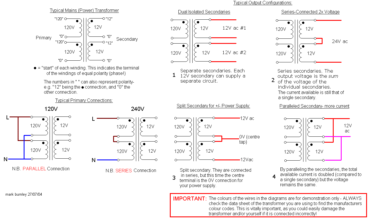
I had actually noticed this myself and, from what I had remembered seeing on this useful tansformer connections document, didn't think it made sense, so thanks for clarifying this!
transformer_connections.gif
link
Harpo said:
Anyway you won't use this mains transformer for this 2 channel preamp project. The center tapped 41.82V AC @ 0.27A winding after fullwave rectification will deliver up to 0.15A of DC power. Your 8 relais alone will draw 8*0.0281A=0.225A, so this doesn't compute.
This is a shame, I really thought I had the right mains transformer for the job! Is it a case of changing the relays, and then working out the resistor values after that? I only included these relays as I followed the BOM  listing, or is it a case of definitely using a larger output power supply?
Harpo said:
The 50.18VAC @0.023A winding would connect at the positive ends of the left out voltage doubler caps C11 and C12 and after fullwave rectification will deliver up to 0.013A of DC power, hardly enough for a single channel phantom supply at worst case condition (48V/(6K8||6K8)=0.014A).
I'm a little confused here i'll be honest.  I thought that these (the 2 red wires secondary coming out of the mains transformer) connected at AC IN for the phantom power?  If not, where exactly should they connect (from whichever mains transformer I end up needing to use)?
Also, do you mean that the C11 and C12 caps should be "left out" of the PSU?

Am I correct in thinking that "after full wave rectification" is that, after the circuit has been engaged, what you then have left to work with in terms of current as an output?

I don't suppose you could help me to begin to understand what the dc power requirements of each pre-amp board needs to be in order to function from being connected to the necessary out of the PSU?  What's that called, current draw? Would be great to know some of the jargon in order to enhance the research I can do myself in terms of beginning to learn what calculations I will need to do. I have a recent understanding of Ohm's law and am trying to understand where specifically to apply it.  ;)
Harpo said:
The schematic shows the relais supplied from a -in your case- 7805 voltage regulator that is fed from this supposed to be +48V rail (+44V from schematic) with voltage dropping resistor R10 in between, transfering 43V to heat. IIRC the wording in the thread already corrected this R10 connection for the relais supply to be better fed from the lower voltage rail.

I would be very grateful if you could please  supply me with the link to that specific thread. :) I have seen this MODified version of the schematic, which I believe is directly related to what you mention. Is it suggested that I go with that modification? and if so, would I need to replace the REG_SW regulator with the 7812 like in that schematic, instead of the 7805 that I currently have installed? Also, would I then use the same value resistors for R1 and R2 which are 22R/5W  according to the modded schematic?
Harpo said:
Your chosen 5V relais coil voltage will draw more power and generate more heat than the 12V coil types, but we'll have to live with it.
So is it okay to go ahead and use them?
Harpo said:
C3 with value 220uF in conjunction with R2 200R set a 1st.order HFP @ 1/(2*PI()*200*220e-6)=3.6Hz in the highest gain setting. Using a 4700uF cap instead would bring this HPF down to 0.17Hz.
You mean on the pre-amp ? So it allows more high frequency to pass with the lesser capacitance on C3? Which is best?

Many thanks again for your response.  Any help at all with any of this is much appreciated. I know it must be frustrating having a complete amateur asking what, to you, are probably daft questions!
I'm trying to look into creating a simulated version of the circuit(s) using software, although trying to master these programs, and designing custom parts/packages, is extremely time consuming along with everything else! Would you recommend doing a simulation? :-\

regards


Ben :D

PS My colleague posted another thread asking the same questions as me, but that is not actually me! Just in case there is any confusion.
 
Sun King said:
Does this reflect on any of the other components when removing the OPA604 from the U1 position?  Or does the circuit remain the same?
The circuit remains the same. (Substituting the DOA and using a NE5534 instead of a OPA604 for U1 would require an additional 22pF between NE5534-pins5/8 in order to make this amp unity-gain stable).

This is a shame, I really thought I had the right mains transformer for the job! Is it a case of changing the relays, and then working out the resistor values after that? I only included these relays as I followed the BOM  listing, or is it a case of definitely using a larger output power supply?
Step by step... You want to operate your two preamps with gar2520 DOAs and opa604 servos. Supply voltage will be +/-16V. Assume about 30mA idle current per DOA rail, 7mA idle current for the opa604. Driving 600R loads (historic gear) assume an increase of supply current needed of about 30mA per DOA rail, a lot less for modern input impedances. Both channels will draw about 140mA, half of this number at idle. Ignoring power for the relais, your transformer looks sufficient for this part. An additional mains transformer could operate the relais power demand.

I'm a little confused here i'll be honest.  I thought that these (the 2 red wires secondary coming out of the mains transformer) connected at AC IN for the phantom power?  If not, where exactly should they connect (from whichever mains transformer I end up needing to use)?
Also, do you mean that the C11 and C12 caps should be "left out" of the PSU?
The AC IN  connector is for the center tapped mains transformer secondaries. There is no shown on-board provision in order to connect an additional FI 50VAC secondary winding. From schematic, the higher raw DC voltage for the +48V phantom rail is generated from the center tapped 42VAC  input voltage by a balanced voltage doubler circuit. Your mains transformer already has an additional  50VAC winding, so this lossy voltage doubler is not needed and you connect your 50VAC winding ends to the positive ends of the left out caps C11 and C12. Supplying two of most (not all) condensor mics, power is far from ample, but should be sufficient. (better use a TL783 or at least a LM317HT instead of a LM317 for REG48 and for +48VDC out instead of +44VDC out use 220R instead of 240R for R7).

Am I correct in thinking that "after full wave rectification" is that, after the circuit has been engaged, what you then have left to work with in terms of current as an output?
yepp. Depending on type of rectification (full-wave bridge, full-wave center tap, full-wave center tap with choke inputs,  full-wave center tap with dual outputs, ..) the form-factor K (1.8 in this circuit) varies and so does the availiable DC current after rectification, IE secondary RMS current = form-factor * DC current load.

I would be very grateful if you could please  supply me with the link to that specific thread. :) I have seen this MODified version of the schematic, which I believe is directly related to what you mention. Is it suggested that I go with that modification? and if so, would I need to replace the REG_SW regulator with the 7812 like in that schematic, instead of the 7805 that I currently have installed? Also, would I then use the same value resistors for R1 and R2 which are 22R/5W  according to the modded schematic?
Yepp (assume the 39VDC at the junction D1/D2/R1/C1 being a typo that would be 29VDC in your case and not exceed the max.input voltage of the REG_SW 78xx) and if the mains transformer could deliver enough power for this load current of 8 relais. Yours is unfortunately not beefy enough for this additional relais coil and status LEDs load.

>> Your chosen 5V relais coil voltage will draw more power and generate more heat than the 12V coil types, but we'll have to live with it.<<
So is it okay to go ahead and use them?
You already have them, so use an additional mains transformer, rectifier and smoothing cap to meet the relais and LEDs supply requirements.

Harpo said:
C3 with value 220uF in conjunction with R2 200R set a 1st.order HFP @ 1/(2*PI()*200*220e-6)=3.6Hz in the highest gain setting. Using a 4700uF cap instead would bring this HPF down to 0.17Hz.
You mean on the pre-amp ? So it allows more high frequency to pass with the lesser capacitance on C3? Which is best?
At this low -3dB cutoff frequencies you don't care. You might decide to use a bipolar cap instead, just in case you want to change your DOA/opamp to a pnp-input type one day, or just short it out because you are using a servo circuit.
 
Thanks again Harpo,

Just to summarise.  What would you do in my situation as the simplest solution?  Would you simply get a higher voltage/current "beefier" mains transformer for the job, and  go with the modification exactly as drawn on the (modded) schematic?  Is this the simplest answer?

At this stage I'm considering just putting in high value resistors in the ??? locations, and then trying to calculate how much voltage/current I have, and then working out how much lower the resistors should be.  Like i've mentioned before, there is a lot of info here I still find overwhelming for my current level of understanding!

Absolutely determined to get these working by next week!

kind regards

Ben

 
Hi Harpo,

I hope you are well?  I'll be honest, I haven't worked on this project for a while (mainly due to having no idea what to do)  :eek: .  Would you mind if I ask you a couple of things, that may be the difference of whether I ever finish these preamps, or not?

What those things would be, if you would be so kind;

If I was to replace all of the 5V relays, with 12V relays (as you suggested earlier), then what would be a good example of a mains transformer (specification wise) that would power both preamps (individually, and together), and supply both of them with phantom power (again, individually and together)?  What specs would be sufficient for that?

If this is the simplest answer of what needs to be done, and a suitable mains transformer is found for the job, would I still need to leave out the C11 & C12 Capacitors?

This would be such useful info if you can help Harpo.

Many thanks

Ben  :D
 

Latest posts

Back
Top