Yes. I have been crazy slammed here.Homestudio said:Hey Jeff, did you see the email I sent?
Thanks
You are using an out of date browser. It may not display this or other websites correctly.
You should upgrade or use an alternative browser.
You should upgrade or use an alternative browser.
[BUILD] CAPI FC526~500 Series~FET Limiter Kit~Official Support Thread
- Thread starter jsteiger
- Start date


Help Support GroupDIY Audio Forum:
This site may earn a commission from merchant affiliate
links, including eBay, Amazon, and others.
Jeremiah Blair
Member
- Joined
- Aug 11, 2018
- Messages
- 10
First time posting. I built a VP26 and a BT50 - both of which sound great. After two successful builds I expected my FC526 XFMR to work perfectly too, but my test point data is off, so I'm looking for some help...please.
Jeremiah Blair
Member
- Joined
- Aug 11, 2018
- Messages
- 10
The voltage at Op Amp +V and -V look okay, not perfect, but I believe they're close enough.
Voltage at TP 9 and MTR Board #11 are spot on. Data at TP1, TP2 and TP3 are significantly off target. What may be wrong or what do I need to investigate?
Note I'm using my DAW to send 24.5mV AC to the unit at 1,000 Hz and using my Extech EX350 DMM for measurements. Using SL-Red Dot Op Amp.
Resistance to -V on DOA socket 3.32 kΩ
Voltage at +V on DOA socket: +15.02 DCV
Voltage at -V on DOA socket: -14.83 DCV
TP9 is -10.01V DC
Meter pt. #11 is 2.501V DC
TP1 is 14.79mV AC (target value = 5.8mV AC)
TP2 is 789mV AC (target value = 117.7mV AC)
TP3 is 4.66V AC (target value = 939mV AC)
Module's Output is 2.511V AC as measured at card edge terminal 4: "Output - " (target value = 1.89V AC)
Module's Output is 2.537V AC measured at pins 1 and 3 of male end of output cable (target value = 1.89V AC)
Thanks,
Jeremiah
From the manual of your DMM:Jeremiah Blair said:The voltage at Op Amp +V and -V look okay, not perfect, but I believe they're close enough.
Voltage at TP 9 and MTR Board #11 are spot on. Data at TP1, TP2 and TP3 are significantly off target. What may be wrong or what do I need to investigate?
Note I'm using my DAW to send 24.5mV AC to the unit at 1,000 Hz and using my Extech EX350 DMM for measurements. Using SL-Red Dot Op Amp.
Resistance to -V on DOA socket 3.32 kΩ
Voltage at +V on DOA socket: +15.02 DCV
Voltage at -V on DOA socket: -14.83 DCV
TP9 is -10.01V DC
Meter pt. #11 is 2.501V DC
TP1 is 14.79mV AC (target value = 5.8mV AC)
TP2 is 789mV AC (target value = 117.7mV AC)
TP3 is 4.66V AC (target value = 939mV AC)
Module's Output is 2.511V AC as measured at card edge terminal 4: "Output - " (target value = 1.89V AC)
Module's Output is 2.537V AC measured at pins 1 and 3 of male end of output cable (target value = 1.89V AC)
Thanks,
Jeremiah
(ACV frequency response is 45~400Hz)
That said I would use 100Hz or 200Hz or something as the test tone and not 1kHz.
Jeremiah Blair
Member
- Joined
- Aug 11, 2018
- Messages
- 10
jsteiger said:From the manual of your DMM:
(ACV frequency response is 45~400Hz)
That said I would use 100Hz or 200Hz or something as the test tone and not 1kHz.
Thanks Jeff. This also explains the note on your test jig (which I clearly didn't heed) about using 400Hz signal if using a DMM.
I've run the tests again using your recommended 200Hz, but my test results continue to be similar - well above target levels:
TP1 = 14.6.mV AC
TP2 = 735mV AC
TP3 = 4.32V AC
Output = 2.31V AC
What areas do you recommend I check? Thanks for your help.
Best,
Jeremiah
Jeremiah Blair
Member
- Joined
- Aug 11, 2018
- Messages
- 10
I decided to look for bad solder joints, and ultimately decided simply to re-flow all of them, but no significant change:
TP1 = 14.1mV AC
TP2 = 710mV AC
TP3 = 4.12V AC
Output = 2.21V AC
:-[
TP1 = 14.1mV AC
TP2 = 710mV AC
TP3 = 4.12V AC
Output = 2.21V AC
:-[
Homestudio
Active member
- Joined
- Feb 5, 2017
- Messages
- 32
Hey Jeff, I'd still like to complete this build. Will I need to buy a new kit?
Jeremiah Blair
Member
- Joined
- Aug 11, 2018
- Messages
- 10
Jeremiah Blair said:I decided to look for bad solder joints, and ultimately decided simply to re-flow all of them, but no significant change:
TP1 = 14.1mV AC
TP2 = 710mV AC
TP3 = 4.12V AC
Output = 2.21V AC
:-[
I realize Jeff is slammed. Does anyone else have knowledge of this unit and can recommend a place to start investigating?
Best,
Jeremiah
Jeremiah Blair
Member
- Joined
- Aug 11, 2018
- Messages
- 10
Jeff, thanks for your help via email: "TP1 is right after the input stage so check the values of the R's to the right of the 2622. "
I tested all the resistors around the 2622 because I wasn't sure which direction was "right" - depending on the orientation of the board. Also, I ended up testing a lot more resistors since I had some time.
I tested the resistors in place on the board with my DMM. I understand tested values of a resistor in circuit may be affected by other components in parallel so I decided the following:
(1) If the DMM results equaled the theoretical value, then I considered them okay.
(2) If the DMM results did not match the theoretical value, then I checked the color scheme to validate whether the resistor is correct. I had difficulty determining colors on some of the resistors, so I also measured resistors of the same value in other positions as another means of determining whether the resistor is correct.
With all of that said, I've attached my data for the resistors that had different measured values compared to the theoretical values and my observations/comments. Do these data make sense to you or what may be wrong?
Thanks for your help.
Best regards,
Jeremiah
Attachments

Jeremiah Blair
Member
- Joined
- Aug 11, 2018
- Messages
- 10

Jeremiah Blair
Member
- Joined
- Aug 11, 2018
- Messages
- 10
Final post for today.
After going back through much of this thread again to see if others have had similar issues I did a couple more things:
(3) I ensured the two 470K and two 470R resistors were not mixed up -- all were correct. I don't think these are anywhere near my issue, but can't hurt to check.
(4) I injected the 200Hz signal at 24.5mV AC again to get voltages at R72, R73 and R42 based on previous advise, (though the issue was different in that case -- low voltage readings at TP1). See attachment.
I tested these because I don't know how to troubleshoot so I'm doing anything I can to get some data that may help.
Thanks,
Jeremiah
Attachments

Jeremiah Blair
Member
- Joined
- Aug 11, 2018
- Messages
- 10
Hi Jeff,
I’m hoping you can help soon. I’d like to place another order for a second channel strip (VP26, BT50, and FC526), but want to finalize this one first.
Thanks,
Jeremiah
I’m hoping you can help soon. I’d like to place another order for a second channel strip (VP26, BT50, and FC526), but want to finalize this one first.
Thanks,
Jeremiah
Jeremiah Blair
Member
- Joined
- Aug 11, 2018
- Messages
- 10
Hi Jeff,
Per your email regarding some misplaced resistors causing the extra gain issue at TP1, I went through and checked every resistor on the main PCB based on the color bands. I did not find any mistakes.
Please review the attached file, which shows the color bands and my reading of the values -- all check out vs. the parts list. I highlighted the resistors nearest the 2622 in purple (for my own benefit) but don't find any errors.
I posted a photo of my main PCB above (Reply #409 on: October 27, 2018, 11:16:01 PM) in case you can spot an issue.
I am hoping you can help.
Best,
Jeremiah
Attachments
Does anyone have any idea what components control the release pot? I have 2 that were workin great, now all of a sudden, on one of them, the release pot doesn’t change the release. It seems to be set to fast all the time. The other works great. Both have been in the same api 6b rack and both have been working fine until recently.
PerspectiveSound
Member
- Joined
- Apr 22, 2018
- Messages
- 6
Hi everyone, I built a new fc526 xfmr, just got the test jig built, powered up, checked opamp connectors and tp9, all good, loaded red dot opamp and began calibration process. In CAPI 511vpr rack with extension jig, test signal from DAW and monitoring signal with Southwire 10040N DMM I ran 200hz sine wave out at 24.5 mV, reading the same in bypass but significantly higher than expected in active with both gain pots all the way up. It was :
output= 2.349 V AC.
Reading the first three test points gave:
TP1= 12.1 mv, TP2= 199.2 mV, TP3= 1.587 V.
I looked through the support thread and did the first step of checking solder points, retouching anything that might be bad but no change. It seemed other people had a similar issue and it seemed possible that resistors near the input could be misplaced but I'm not sure how to test them on the board other than by colored bands. Comparing my board to pictures online of working units I can't see any differences. I'm still a beginner as far as electronics but I have also built 4 vp28s and a bt50 and they all came out well so I'd love to figure out what's wrong. I wondered if the user Jeremiah Blair had any luck tracking down his issue since it seemed similar although with different specific values. Also of course I am limited by my equipment, it is possible that the build is fine and my DMM is not accurately reading the voltage or some other outside issue I'm not thinking of. Any ideas anyone here could give me would be very appreciated, thank you!
I am wondering if there is a measurement error reoccurring here.
The -30dB test signal should be verified with a DMM set to ACV. Before even looking at the comp or running signal to it...make sure you truly have the proper sine wave level from your generator of choice. With your DMM's black probe to XLR pin 3 and red probe to XLR pin 2, your DMM should show 24.5mV. That is .0245V AC. If the frequency response of your DMM will not read 1kHz then use 200Hz or 400Hz.
When checking the audio path of the FC526 XFMR, the above 24.5mV AC signal will be present at the bottom of R73 (black probe) and R71 (red probe) when the unit is in active mode. This is right after the relay circuit and essentially a "hard wire" to the input XLR of the rack. If your signal here does not match your signal generator then there is a relay bypass circuit problem. No need to go any further with audio path readings.
PerspectiveSound
Member
- Joined
- Apr 22, 2018
- Messages
- 6
Yep, that's exactly what it was, I have a TRS patchbay and I think I was measuring tip to sleeve instead of ring, I checked the pinout and noticed the test signal level was lower than I had been using, from there everything was perfect, just finished calibration. Can't thank you enough, Jeff!
dansvillalba
New member
- Joined
- Jan 9, 2019
- Messages
- 1
Hi! Jeff
A Few days ago I finished to build and calibrated my two FC526 compressors.
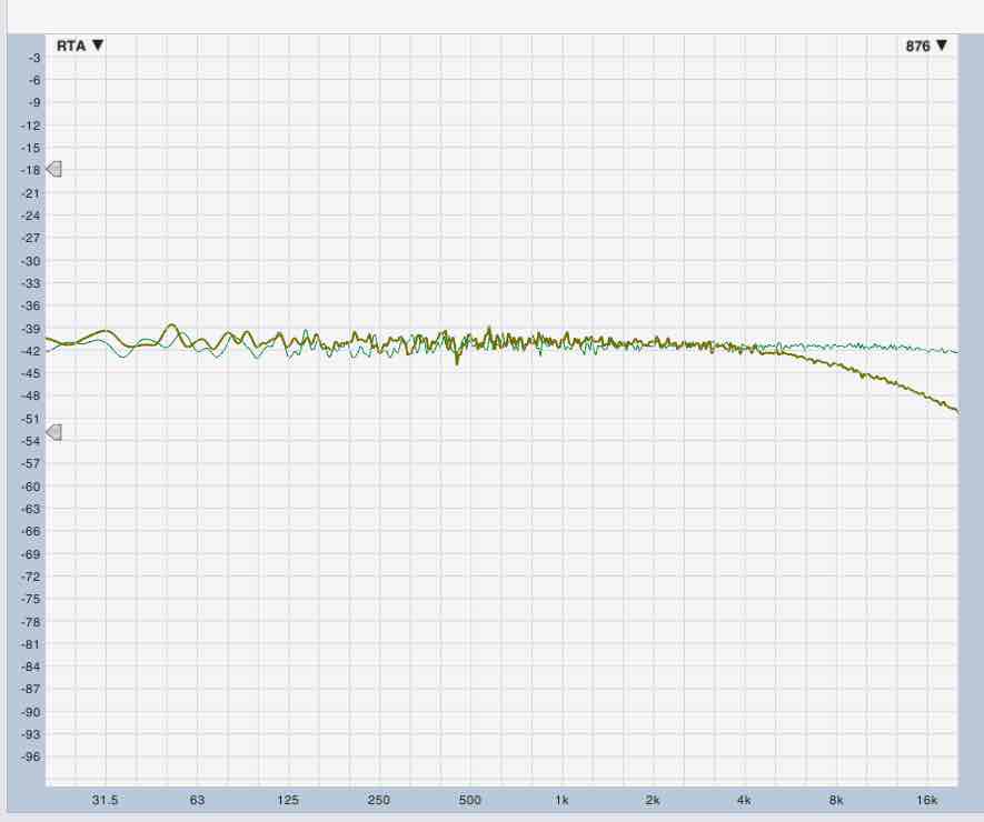
Making frequency response test in both compressors , I noticed that one of them had a roll of in high frequencies.
Why is this happening? Did I make anything wrong? :-\
Attached pictures with frecuency response of two compressors
A Few days ago I finished to build and calibrated my two FC526 compressors.
Making frequency response test in both compressors , I noticed that one of them had a roll of in high frequencies.
Why is this happening? Did I make anything wrong? :-\
Attached pictures with frecuency response of two compressors
Yeah, looks like something is not right with one of them. You will have to visually compare the 2 units and see where you made the error.dansvillalba said:Hi! Jeff
A Few days ago I finished to build and calibrated my two FC526 compressors.
Making frequency response test in both compressors , I noticed that one of them had a roll of in high frequencies.
Why is this happening? Did I make anything wrong? :-\
EDIT-Confirmed every piece was correct 3 times, touched up any suspect looking joints on the board, and the Dt05 op amp, and now we're golden. So no help needed here, just wanted to update so others who have a similar problem can read my solution.
Hey Jeff so having a little grief here with only one of the 4 comp's I've built... all the other 3 are great, but here's the problem with the one.
Pre-calibration figures are great and all check out. When I get to the q bias and flip the bypass to act I don't get the usual -5ish dbfs instead I get something way lower.
So something's up with the audio path....
Following the steps of the audio path test these are the figures I'm getting
Tp1- 6 mV AC
Tp2- 3.2mV AC
Tp3-24.8 mV AC
So something apparently is up with TP 2 which if I'm not mistaken points to the DT05.
Now I thoroughly have checked every component on the Dt05 and everything is exactly as it should be.( twice to be sure) One a direct comparison with the other DT05 op amps in the other working modules as well as direct against the BOM.
Now Yesterday I checked every resistor on the meter's ( even though they came out fine in pre calibration) and the main pcb. Everything appears to be as it should so it's really got me scratching my head here.
I'm going to go through and check again to make sure every resistor is correct, I've made the mistake and had a similar result in the past when the 470R And 470K resistors were switched, but that doesn't appear to be the case this time. Any particular place I should look jeff?
Perhaps there's a weak joint somewhere? The gar2520 is tested and fully functional as well.
Similar threads
- Replies
- 4
- Views
- 643
- Replies
- 56
- Views
- 15K
- Replies
- 43
- Views
- 10K
- Replies
- 18
- Views
- 3K
- Replies
- 122
- Views
- 36K