helios 22113

GroupDIY Audio Forum

Help Support GroupDIY Audio Forum:

This site may earn a commission from merchant affiliate links, including eBay, Amazon, and others.

Rocinante

Well-known member
Joined
Jan 17, 2014
Messages
1,132
Location
Minnehopeless
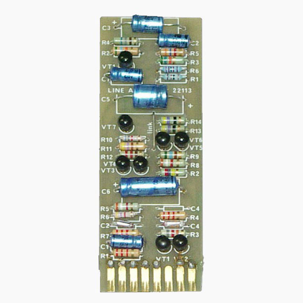
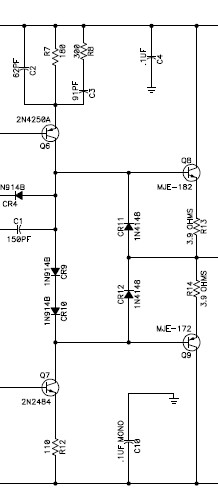
  After building and using the Ruff Records Helios 69 Eq I developed a pretty nasty heliobsession.  After some exchanges with several other members I decided to take a try at redrawing the 22113 board so I could build the mic preamp section with the hopes of marrying it to  either Ian's Helios 69 eq boards or James' easy 69.  Or maybe just a stand alone mic pre or PTP or just perfboard the eq like in some of the originals.  At any rate I read the 22113 is capable of driving an output transformer as all the other cards (2128, 15ci, 10cc) went unbalanced out and have heard a lot of interesting things about the pre amp section.  I am fortunate that other members share my enthusiasm and through our collected sharing obtained a decent amount of incredibly interesting information I redrew the circuit.  Hopefully it's right.  Where I am really lost is regarding the 7 (and sometimes 8?) Micro Electronics transistors that went into the 22113 and what there modern equivalents would be?  I have read the informative 2007 R/E/P/ thread (which actually has many contributors from this forum) and in there Tony Arnold (current owner of Helios-Electronics) is asked about the 7 transistors equivalents of which he replies with: "I've already shown the USA equivalents...", but for the life of me I can't find where he has published that. 
So does anyone know what a good replacement for:
ME0412 PNP
ME4102 NPN
ME4101 NPN
ME6101 NPN
ME0402 PNP
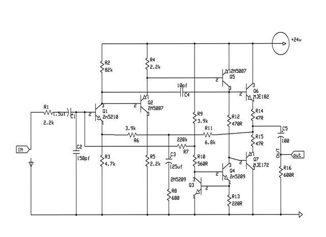
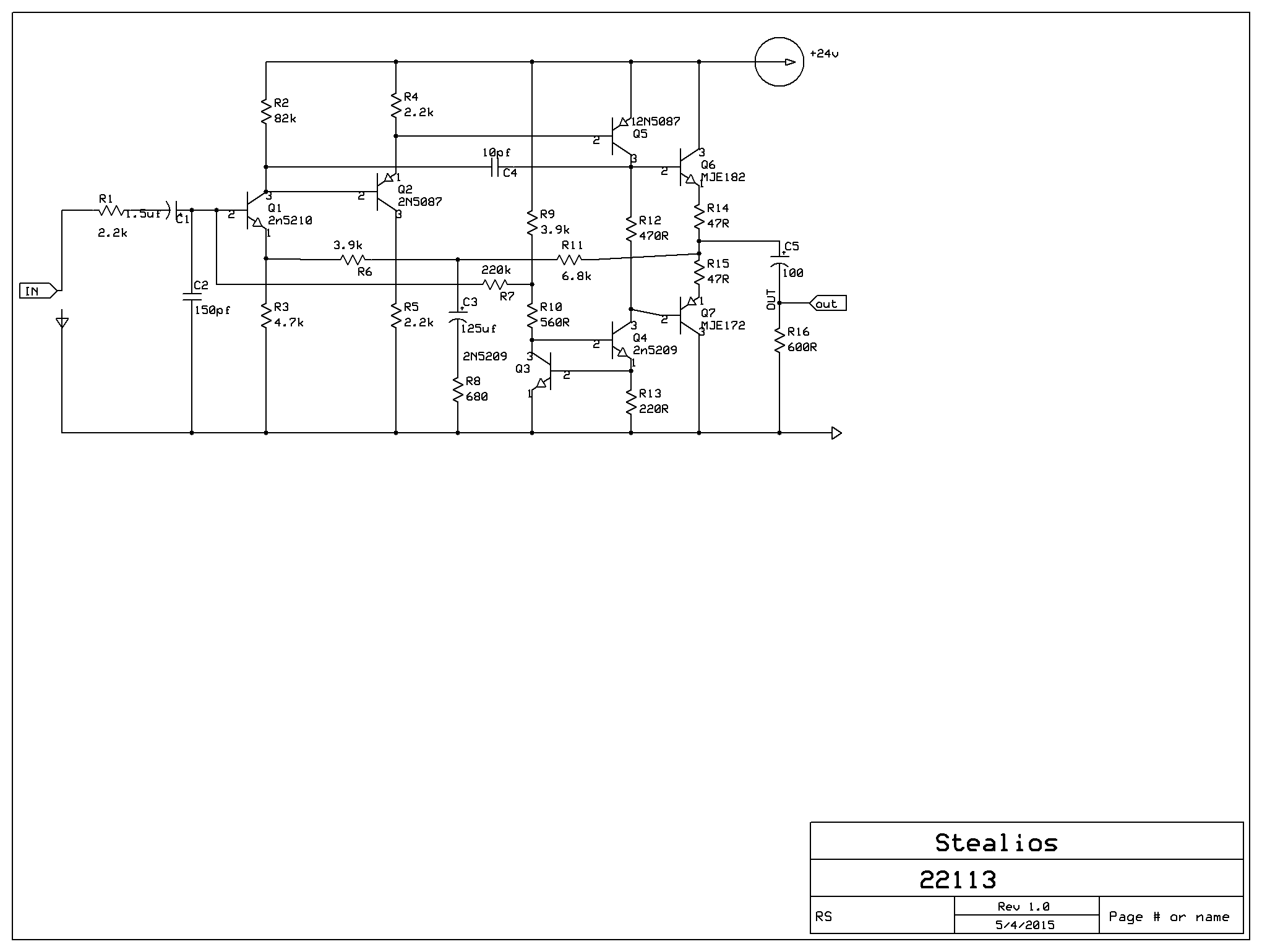
For instance; I was gonna use NTE-123ap for the me4102s as reading the datasheet it seemed pretty close to the same specs but I am really a totally ignorant schmuck and have never done anything like this before so I would probably be wrong.  Anyways here's a redrawing of the 22113 schematic that I made.  If anyone could please point me in the right direction that would be just great.    Thanks in advance. *Edit- updated schematic to show suggested changes.
TZZmPud.png
 
Interesting to see 7 holes with parts from *four* different registries: 2N, BC, 2SC, and NTE.

R.G.'s Law: When in doubt, stuff a 2N5088, it should work. (Unless it wants a PNP.)

In this case, since you are ordering, I would consider:

2N5089 small NPN
2N5087 small PNP

2N4401 BC550 NPN output
2N4403 BC560 PNP output

Even with full 600 Ohm loading, you could probably use 2N508_ in all the holes.

If you are going to short the output you need beefier output devices. Find what Jensen is using in the 990.... over-kill but affordable.

Check my numbers-- I may be typo-ing. Check ALL pinouts; many will be different than the boards you are copying.
 
Thank you.  Fortunately I have some 2n508*'s in my bin. It's worth mentioning someone over at GS made the same suggestions so it seems I have a solid basis from which to pick from and work with.
I'll stay mindful of the pin outs.
Time to start ordering and perfboarding.
Thanks again.
 
PRR, (or whoever )
I have taken your suggestions and have been reading a bunch on the 990 and see that it calls for (and Mnats uses) mje-171 and mje-181 at the output.
LQ5AGCf.jpg

Questions;
I see that theres a diode bridge  consisting of four 1n914b's before the two transistors and if I'm understanding what ive read correctly this is for heat dissapation so I shouldnt need to include it correct? *edited

I had read at DiyAudio that  "CR9 and CR10 set the Vbe delta for the output devices. But the anode cathode voltages are established by the currents flowing in Q6 and Q7. Various offsets prior to Q6 and Q7 can affect the output offset in addition to Vbe mismatch in the output devices offset"
In the case of the 22113 should I be including the diode bridge and be concerned with what Q6 and Q7 are doing?

The 990 needs both positive and negative and thus the transistors use both rails. Do i need to modify anything or can i just plop them in keeping mindful of the pin outs and so treat the 0v like the -12 thru -24v that is in the 990?
Finally; the 990 has two 3.32R resistors at the output after the transistors whereas in the 22113 they 47r should i change it to what the 990 uses?

I will be the first to say I'm in over my head and so thanks a bunch for answering such rudimentary questions. This is how I learn and I consider myself still pretty green.  I don't necessarily paint by numbers much anymore but I'm not a ton of steps past that point.

Also I will update the schematic with the correct transistors shortly. I have almost finished the layout in Freepcb and fortunately have some friends double checking my work, so if it looks good will probably make a couple of boards if anyone's interested. I'm considering using Oshpark unless I can find a cheaper solution for short runs. 

 
> theres a diode bridge.....CR9 and CR10 set the Vbe.....needs both positive and negative....

No, don't steal the 990's whole output stage. It is different, and a franken-amp would be different from what you love about the Helios. I just meant that the *devices* used have good gain, speed, ample robustness, and are readily available.
 
http://groupdiy.com/index.php?topic=55283.0


if you read through my project thread there's tons of helios information. I still have some boards if you want a few to play with.

 
Oh its your thread that made me decide to take this on, specifically when Ian said
"The circuits you have posted so far are unfortunately not man enough to drive an output transformer. For that you really need to use the high level line amp..."
And hence here we are.
Your boards might come in useful dont get me wrong but I am planning on tying this to a type 69 eq (probably Ramshackles Easy69) and tapping the 600:600 output transformer thats had a sowter provision made for it on his board. I am also going to build a dual channel mic pre/DI. Reading that really awesome Helios thread on R/E/P it seems the Island module's (22113)  DI was integral to the tone of a ton of the guitar driven bands of the 70s so that seems worth it enough to me of at the very least serious exploration.  Depending on cost and how it sounds I might do more channels  but thats getting ahead of myself quite a bit.
I'm gonna prod David from Cinemag and see what he thinks of using their 1:10 input transformer (cmmi-10c I believe) in place of the Lustraphone/Sowter.
 
Very cool before I finished the pcb I did add the buffer to the end of the circuit I'm not sure if that shows up in the thread. I wasn't using a output transformer just 1/4 unbalanced out so I wasn't worried about driving one

I also built one of Ian's helios type 69 eqs. Just adding a gain stage is all that's left. Have some one bottle pcbs laying around I'll probably use but I'm definitely gonna play with the helios boards for this as well. I'll keep ya posted  :)
 
Yes the 4th transistor. I struggled with it personally. I still am experimenting with your boards and I believe they would be excellent line ins which could make them very useful.
I know there's also been some modifications done buffering the output by various people  (including Igor whom never included it in his he69?) but I know for certain Ian knows his stuff and have used the remake Helios preamp ( oh how i wish i had looked inside) and liked it very much.
 
Oh your gonna dig that Eq.  Especially with the tube gain stage.
I don't have any samples on hand ATM but for electric and acoustic guitars Ian's type 69 with tube gain stage is just awesome.
Totally an effect EQ but that effect is tremendous and good.
It's  not something I put on everything but definitely something I have used in every session .
 
That's awesome I'm super excited to get it finished! What did you do for a front panel? I was just gonna get one done from front panel express or something. Looking forward to this helios project would love to get some other pre amp boards to play with
 
I posted my front panel at the Helios 69 thread.  In respect to the Sun God (as well as the god of aged scotch and god of tube compressors) I imitated the original.  Pm if you need the file
 
Looking at the pic of this 22113 card from Orphan Audio I see an 8th transistor which has a brief mention with no real explanation somewhere in that 160 page R/E/P thread.  Is that whole section past C5 the output buffer?
*edit: A member informed me it is probably the hp filter.
VJqWPzb.jpg

It's the only 8 transistor card I have seen yet.
I understand that Helios modules were never supposed to leave the console but I also understand that many people have made them standalone units without removing the essence (for lack of a better word) of what we so like about the Helios.
This is what I am trying to achieve. 

Again thanks in advance. 
Dylan
 
I've come a bit further along after verifying some details and blabbing with a few people regarding the Helios amp and am currently in the process of sending the layout off to OshPark to get a couple of boards made.  David from Cinemag was a big help and suggested I might want to try a 1:2 for the output transformer which was interesting while Jim Dowler thought that a lot of the Helios sound came from the Lustraphone transformers.  In his words: "... it has a peak at around 32Khz which means it is not flat at 20Khz (bit like an Air control )"
Well I don't know if I am into spending that much money just yet as I am sure they are not cheap.   
He along with others also advised at running it at 32-36v.
Dave Amel from Anamod (who make a Helios mic pre recreation as well as a ton of other cool gear) thought it should work and pretty much echoed others in saying the output was a bit overkill but should drive 600 ohms.
Cool. 8)
Nevertheless it's been interesting.

lzT8SKfl.jpg
 
Voltage drop resistor? Noise suppresion for emitter?  I don't really know but I've seen numerous designs from the 60s using that as well (ADI 44 and 21 come to mind) Honestly the answer is its in the 22113 schematic and so I included it. Im sure someone smarter than me can tell you?
 
Appears to me to be a series output resistor, for stability concerns; not a load.
 

Attachments

  • output.jpg
    output.jpg
    19.4 KB · Views: 104
That's the one. Neat. Where is that drawing from if you don't mind?  It doesn't look like any of the 22113 schematics I have seen.
 
Success!
With the exceptionally observant eye of member Gearsix the circuit works and not only that; it's got balls!!
CMMI-10c wired 1:10 going into the 22113 circuit
Gain is controlled by a Grayhill 1 pole 12 T in place of R8
Mje171 and 181 seem to work great in the output; thanks PRR.  Unfortunately for me I had sent the OshPark order through several hours before Gearsix noticed that the pin-outs of the to-126 case output transistors were different from the to-92 in it that their base and collectors are switched.  It wasn't too much of a problem to twist the long legs on the transistors and the final version has the correct pin-out and trace.
The output is CMOQ-2s wired 1:2
24v was fine but 32v sounded clearer.  I am still experimenting but it is full and punchy and has enough gain for a year.
It's good.
"Well, I’ll be harrowed, cultivated, pruned, gathered into a pile, burned, picked off a tree, and let me see, what else? Thrown into a box, cut off a vine and eaten grape by grape by a girl in her teens."
- W. Saroyan

 
Back
Top