Thanks a lot!audiophreak said:Yes , 20mm pots , I believe the switch post is 3.3mm square
You are using an out of date browser. It may not display this or other websites correctly.
You should upgrade or use an alternative browser.
You should upgrade or use an alternative browser.
calrec PQ1549 help thread
- Thread starter JayDee
- Start date


Help Support GroupDIY Audio Forum:
This site may earn a commission from merchant affiliate
links, including eBay, Amazon, and others.
Hi!
I'm ordering caps at Farnell, and have little idea if what I choose is wise or not.
Please tell me if anything looks like bad budget or quality decision:
100nok = 11.1 Eur = 13.1usd
I'm ordering caps at Farnell, and have little idea if what I choose is wise or not.
Please tell me if anything looks like bad budget or quality decision:
100nok = 11.1 Eur = 13.1usd
Linje Partnumber Ant. Prod. delenr. Beskrivelse Price PriceTot
1 9708367 25 MCCB1C336M2DCB MULTICOMP-MCCB1C336M2DCB-CAP, TANT, 33UF, 16V, RAD kr 5,10 kr 127,50
2 1848399 12 EEUFM1H220 PANASONIC-EEUFM1H220-CAP, ALU ELEC, 22UF, 50V, RAD kr 0,64 kr 7,68
3 1848463 4 EEU-FC1H470 PANASONIC-EEU-FC1H470-CAP, ALU ELEC, 47UF, 50V, RAD kr 0,78 kr 3,12
4 1219466 6 EEUFM1E101 PANASONIC-EEUFM1E101-CAP, ALU ELEC, 100UF, 25V, RAD kr 1,45 kr 8,70
5 9411674 25 MCCHU5220J5 MULTICOMP-MCCHU5220J5-CAP, CER, C0G/NP0, 22PF, 50V, RAD kr 0,571 kr 14,275
6 1141797 5 F101K25Y5RP6UK5R VISHAY BC COMPONENTS-F101K25Y5RP6UK5R-CAP, MLCC, Y5R, 100PF, 2KV, RAD kr 0,92 kr 4,60
7 1006031 45 MKS2D031001A00KSSD WIMA-MKS2D031001A00KSSD-CAP, FILM, PET, 100NF, 100V, RAD kr 1,10 kr 49,50
8 1005997 5 FKS2D016801A00KSSD WIMA-FKS2D016801A00KSSD-CAP, FILM, PET, 6.8NF, 100V, RAD kr 1,40 kr 7,00
9 1006044 1 MKS4G022203C00KSSD WIMA-MKS4G022203C00KSSD-CAP, FILM, PET, 22NF, 400V, RAD kr 1,50 kr 1,50
10 1854848 10 ECQV1J683JM PANASONIC-ECQV1J683JM-CAP, FILM, PET, 68NF, 63V, RAD kr 0,94 kr 9,40
11 1890155 10 MKS4D031502B00KSSD WIMA-MKS4D031502B00KSSD-CAP, FILM, PET, 150NF, 100V, RAD kr 1,35 kr 13,50
12 1006039 5 MKS2C036801E00KSSD WIMA-MKS2C036801E00KSSD-CAP, FILM, PET, 680NF, 63V, RAD kr 3,20 kr 16,00
13 1215481 5 BFC236845104 VISHAY BC COMPONENTS-BFC236845104-CAP, FILM, PET, 100NF, 250V, RAD kr 2,17 kr 10,85
Totalsum for varer: Nkr 273,625
musika
Well-known member
Hello all,
I'm building this EQ for a college project, and I have a few questions. I have 3 out of 4 filter sections on a breadboard, and I am running a signal from a Neutric audio analyzer through the circuit. It can sweep and show the frequency response of each filter, which is very handy.
Question 1: What is the intended signal level for the calrec? Is it -10dBV or is it the more traditional pro line level? The answer to this may be the answer to my second question.
Question 2: While all the filters notch beautifully, when boosting some of them plateau at a certain point and stay flat at the top. This is obviously not the intended response, or the notches would look the same. Does anyone have any idea why this might be?
I have referred to the original calrec schematic for the proper component values where the original schematic was in error. I will post a corrected schematic after my project is complete. I will also be required to design a new PCB layout which I will share for anyone curious.
cidw
cidw said:Question 1: What is the intended signal level for the calrec? Is it -10dBV or is it the more traditional pro line level?
Original intended level is a bit abstract, as this unit is cut out of the mixer's internal gain structure.
We have been using this eq at "classic" studio levels, that is, +4dB where there's still some 15-20dB headroom depending on your psu voltages.
The "flattening" of boost curves is probably clipping because of excessive levels - did you listen?
Note that the big cut/boost range of this unit makes it easily overloaded at full-level tone sweeps. In general, run eq sweeps at -20dB for necessary measuring headroom.
Jakob E.
yes
Maybe its just another silly question, but could be done this simply replace them pin-to-pin, no need to "cross wiring?"gyraf said:
That would depend on switch pin layout. Consult schematic?
Jakob E.
Jakob E.
jasonallenh
Well-known member
I'm about to start on a stereo pair of these. Did we decide that the 16V electrolytics are ok? It seems like some folks used them with no problems, but I suppose that is determined by your chosen operating voltage. I plan to run mine at +/-18, so I'd prefer to get it right the first time. All my Electros are at 50V, so I'm sure I'm fine.
I'm putting a Mouser Project BOM for this (I haven't been able to find one), so I will post it when I'm done. I've got to find a way to make myself useful around here!
I'm putting a Mouser Project BOM for this (I haven't been able to find one), so I will post it when I'm done. I've got to find a way to make myself useful around here!
jasonallenh
Well-known member
There is a 22uF electrolytic cap on the Rev 5 board that doesn't exist on the Rev 4... I'm assuming it was added as part of the insert point. Can I use a jumper in place of this I if I don't intend to use the insert point?
I ran out of the correct value... And I don't want to hold up build for two caps =\
I ran out of the correct value... And I don't want to hold up build for two caps =\
I don't remember what that capacitor may have been - but I don't think any of them can safely be jumpered.
If you have any of larger value, just put that in...
Jakob E.
If you have any of larger value, just put that in...
Jakob E.
jasonallenh
Well-known member
Thanks Jakob!
Greetings all,
Loving this thread and this project and everyone's generosity and passion.
My PCB's are almost fully populated.
Would someone please be kind enough to clarify a couple of issues:
1. Are the two resistors highlighted in the attached pic the correct ones ones to switch from 10k to 22k? I have looked at the schematic - I just want to confirm as there is a cluster of four 10k resistors at the input....not sure which two are the ones...
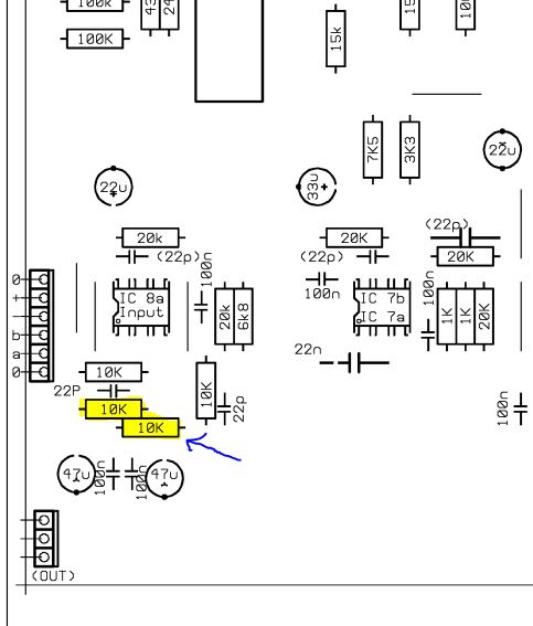
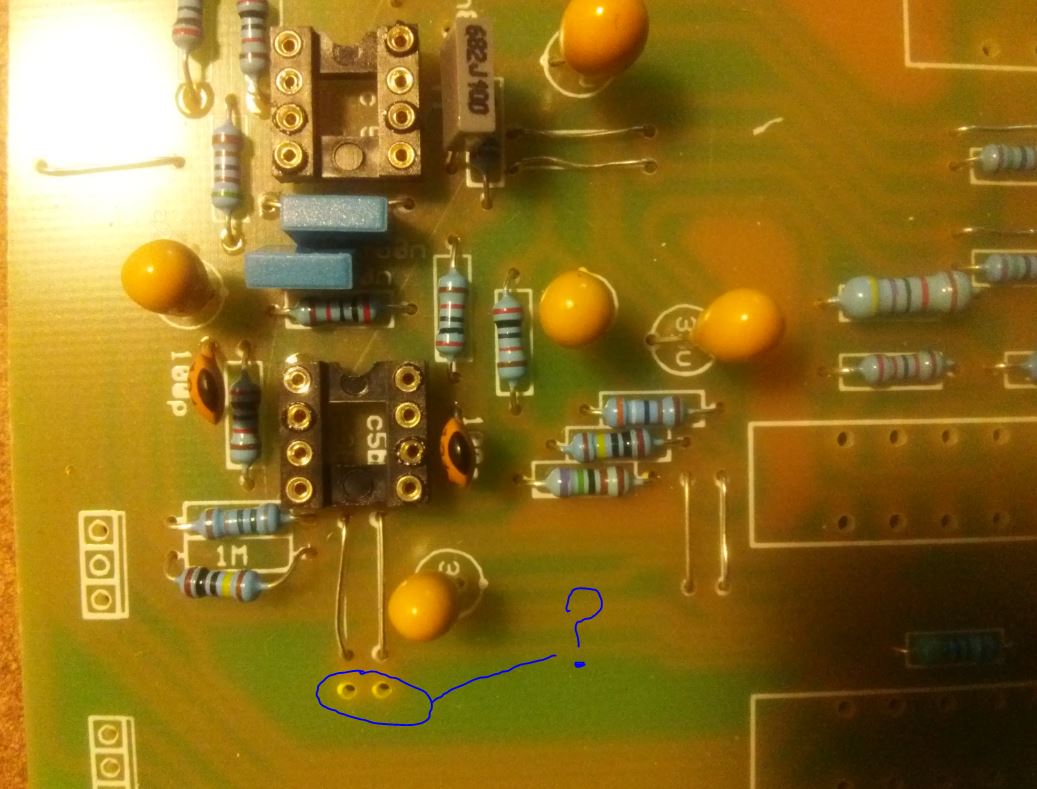
2. What component is meant to go in the spot indicated in the pic below? There are no silkscreen markings to indicate a component or value...just two lonely solder holes that look like they are waiting for a cap.
Please excuse my untidy board and the slightly cooked IC sockets!
Thanks in advance.
Nolan
Loving this thread and this project and everyone's generosity and passion.
My PCB's are almost fully populated.
Would someone please be kind enough to clarify a couple of issues:
1. Are the two resistors highlighted in the attached pic the correct ones ones to switch from 10k to 22k? I have looked at the schematic - I just want to confirm as there is a cluster of four 10k resistors at the input....not sure which two are the ones...
2. What component is meant to go in the spot indicated in the pic below? There are no silkscreen markings to indicate a component or value...just two lonely solder holes that look like they are waiting for a cap.
Please excuse my untidy board and the slightly cooked IC sockets!
Thanks in advance.
Nolan
jasonallenh
Well-known member
unqlenol-
I don't know what that is for, but leave it empty... it will work without putting anything there.
=jh=
I don't know what that is for, but leave it empty... it will work without putting anything there.
=jh=
jasonallenh
Well-known member
So I've completed two channels, and I've got some troubleshooting to do! I took a look at all of my IC voltages, and they're quite healthy, +/- just under 18V. I also fed the unit white noise and viewed the resulting processing with my DAW to see what is and isn't working. I double-verified my component values/locations/polarities, and they are are correct.
Channel one- I had the extra gain issue, replaced the specified 10K resistors with 22k, and it's PERFECT. This is definitely the way to go. My low filter, low mid, and hi mid are all working flawlessly. My issue is the high band. The gain control has no effect (meaning I also can't tell if the frequency select is working) and activating the shelf switch results in a pop and an almost complete loss of signal. I've double-verified my part values, and I know they are correct. I've also reheated some solder joints, and tried to clean off as much solder flux from the board as I can. Has anyone had a similar issue?
What could cause the full signal to pass through the hi filter unprocessed while also not allowing the filter to process the signal? Bad IC (I swapped ICs 5a and 5b and didn't see a change...)? A short somewhere in series with the gain pot?
Channel two- Not so close The low and low mid are fine (seems like it is for most folks, too). The high mid band is allowing the full signal to pass unprocessed (like the hi band in channel one). The gain controls do nothing.
The high band seems to be influencing the signal all the way across the frequency range. Making changes to the high band actually allows me to get to 'flat' when using white noise, but not when the gain pot is at '0.'
I will certainly continue to check for shorts in the meantime... but any hints will be appreciated!
Channel one- I had the extra gain issue, replaced the specified 10K resistors with 22k, and it's PERFECT. This is definitely the way to go. My low filter, low mid, and hi mid are all working flawlessly. My issue is the high band. The gain control has no effect (meaning I also can't tell if the frequency select is working) and activating the shelf switch results in a pop and an almost complete loss of signal. I've double-verified my part values, and I know they are correct. I've also reheated some solder joints, and tried to clean off as much solder flux from the board as I can. Has anyone had a similar issue?
What could cause the full signal to pass through the hi filter unprocessed while also not allowing the filter to process the signal? Bad IC (I swapped ICs 5a and 5b and didn't see a change...)? A short somewhere in series with the gain pot?
Channel two- Not so close
The low and low mid are fine (seems like it is for most folks, too). The high mid band is allowing the full signal to pass unprocessed (like the hi band in channel one). The gain controls do nothing. The high band seems to be influencing the signal all the way across the frequency range. Making changes to the high band actually allows me to get to 'flat' when using white noise, but not when the gain pot is at '0.'
I will certainly continue to check for shorts in the meantime... but any hints will be appreciated!
jasonallenh
Well-known member
OK, so in looking at the schematic and I'm realizing that according to the schematic, the Shelf Hi switch is supposed to have two decks with no connection when ACTIVATED. On the PCB, there is only one? Is this correct? My problem is definitely in the vicinity of the shelf switch (ic5b/ic3b gets hot too). Im using the C&K 611-f4ueeau switch (should be fine) but I'm missing something here...
jasonallenh
Well-known member
I'm at my wit's end :-[ It seems like everything I do has no effect... Hi band is still effectively bypassed until I hit the hi-shelf switch, then the signal drops out. I've been tracing the area around the switch and gain pots and can't find anything wrong. I'm just going in circles now.
Similar threads
- Replies
- 12
- Views
- 3K
- Replies
- 11
- Views
- 2K
- Replies
- 89
- Views
- 7K